

The Yokogawa AED5D Digital Terminal Board is a high-density field wiring interface designed for Yokogawa FIO systems. It provides a reliable connection between digital I/O modules and field devices, supporting both single and dual-redundant controller architectures. With 32 digital signal terminals, M4 screw connections, and compatibility with multiple Yokogawa digital I/O modules, the AED5D simplifies cabinet wiring while improving maintainability and system reliability. Proper installation, wiring, grounding, and commissioning are essential for stable long-term operation.
Contents
- 1. AED5D Terminal Board Overview
- 2. Technical Features
- 3. Typical Industrial Applications
- 4. Installation Planning
- 5. Hardware Inspection
- 6. Installation Environment
- 7. Terminal Board Mounting Procedure
- 8. Digital Field Wiring Installation
- 9. Grounding and Shielding
- 10. Connection to Digital I/O Modules
- 11. Wiring Verification
- 12. Commissioning Procedure
- 13. Functional Testing
- 14. Preventive Maintenance
- 15. Practical Installation Case
- 16. Frequently Asked Questions
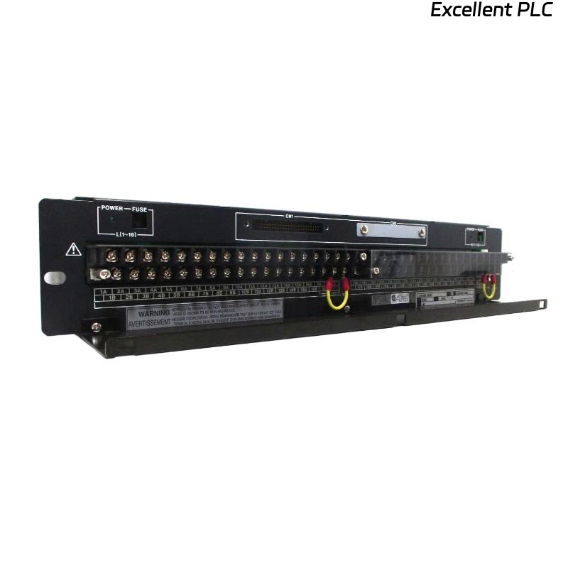
AED5D Terminal Board Overview
The AED5D is a 32-channel digital terminal board for Yokogawa FIO systems. It supports both single and dual-redundant digital I/O module configurations and is compatible with ADV151, ADV551, ADV161, and ADV561 modules. The terminal board uses M4 screw terminals and connects to compatible digital I/O modules through AKB331 or AKB337 connection cables, depending on the module type. Two AED5D terminal boards are required when connecting one ADV161 or ADV561 module. :contentReference[oaicite:0]{index=0}
Technical Features
- 32 digital signal terminals
- M4 screw terminal connections
- Supports single and dual-redundant systems
- Compatible with ADV151, ADV551, ADV161 and ADV561
- AKB331 or AKB337 cable interface
- Compact panel installation
Typical Industrial Applications
- Digital input marshalling
- Digital output wiring
- Emergency shutdown systems
- Motor control centers
- Process automation cabinets
- Oil and gas facilities
Installation Planning
Careful engineering preparation helps ensure efficient installation and simplifies future maintenance.
- Review wiring drawings
- Verify I/O assignments
- Confirm cable schedules
- Prepare terminal labels
- Inspect cabinet layout
Hardware Inspection
- Verify model number
- Inspect terminal screws
- Check connector condition
- Inspect insulation
- Verify mounting accessories
Installation Environment
- Maintain cabinet ventilation
- Avoid excessive humidity
- Protect against vibration
- Separate signal and power cables
- Keep cabinet interior clean
Terminal Board Mounting Procedure
- Disconnect cabinet power.
- Install the AED5D on the designated mounting panel.
- Secure all mounting screws.
- Connect the appropriate AKB connection cable.
- Verify connector locking.
- Inspect mechanical alignment.
Digital Field Wiring Installation
Correct wiring practices improve signal reliability and simplify future troubleshooting.
- Label every field conductor
- Separate digital and power wiring
- Verify cable continuity
- Inspect insulation resistance
- Tighten all terminal screws correctly
Grounding and Shielding
- Use single-point grounding
- Ground cable shields correctly
- Avoid ground loops
- Verify cabinet bonding
- Inspect earth continuity
Connection to Digital I/O Modules
INSTALL TERMINAL BOARD
CONNECT AKB331 OR AKB337
VERIFY CONNECTOR LOCK
CONNECT FIELD SIGNALS
VERIFY TERMINAL NUMBERS
CHECK CHANNEL ASSIGNMENT
Wiring Verification
- Confirm terminal numbering
- Verify wiring continuity
- Inspect polarity where applicable
- Check cable routing
- Review engineering drawings
Commissioning Procedure
- Apply cabinet power
- Verify module communication
- Test digital inputs
- Test digital outputs
- Record commissioning results
Functional Testing
- Verify all 32 digital channels
- Confirm field device operation
- Inspect controller diagnostics
- Monitor communication status
- Validate complete signal transmission
Preventive Maintenance
- Inspect terminal screws every six months
- Check cable insulation annually
- Clean cabinet interiors
- Verify grounding connections
- Maintain current wiring documentation
Practical Installation Case
During commissioning of a compressor control cabinet, several digital output channels failed to energize field relays despite normal controller diagnostics.
Inspection confirmed that the connected ADV551 module was functioning correctly. Engineers found that the AKB331 cable connector between the module and the AED5D terminal board had not been fully locked during installation.
After reconnecting and securing the cable:
- All 32 digital channels operated normally.
- Controller diagnostics remained healthy.
- Field relays energized correctly.
- The cabinet was successfully commissioned without replacing any hardware.
Frequently Asked Questions
Which Yokogawa modules are compatible with the AED5D?
The AED5D supports ADV151, ADV551, ADV161, and ADV561 digital I/O modules. ADV151 and ADV551 use the AKB331 connection cable, while ADV161 and ADV561 use the AKB337 cable. Two AED5D boards are required for one ADV161 or ADV561 module. :contentReference[oaicite:1]{index=1}
How many digital channels does the AED5D support?
The terminal board provides one 32-point digital terminal interface using M4 screw terminals for field wiring. :contentReference[oaicite:2]{index=2}
Does the AED5D support redundant systems?
Yes. The AED5D is designed for both single and dual-redundant Yokogawa FIO configurations. :contentReference[oaicite:3]{index=3}
Summary: Proper installation of the Yokogawa AED5D Digital Terminal Board requires correct mounting, organized digital field wiring, secure AKB cable connections, reliable grounding, and comprehensive commissioning. Following these procedures ensures dependable signal transmission, simplified maintenance, and stable operation in Yokogawa FIO control systems.