

The Yokogawa ADV559 Digital Output Module is a 32-channel isolated transistor output module designed for industrial automation and Yokogawa CENTUM systems. It delivers reliable 24 VDC ON/OFF control for relays, solenoid valves, contactors, indicator lamps, and other field devices. Most installation issues are caused by incorrect wiring, unsuitable load connections, or improper controller configuration instead of hardware failure. A structured Installation Guide ensures efficient Setup and Commissioning while maximizing long-term operational reliability.
Contents
- 1. ADV559 Digital Output Module Overview
- 2. Technical Features
- 3. Typical Industrial Applications
- 4. Installation Planning
- 5. Hardware Inspection
- 6. Installation Environment
- 7. External Power Supply Verification
- 8. Module Installation Procedure
- 9. ADV559 Wiring Installation Guide
- 10. Grounding and Shielding
- 11. Controller Configuration
- 12. Commissioning Procedure
- 13. Functional Verification
- 14. Preventive Maintenance
- 15. Practical Commissioning Case
- 16. Frequently Asked Questions
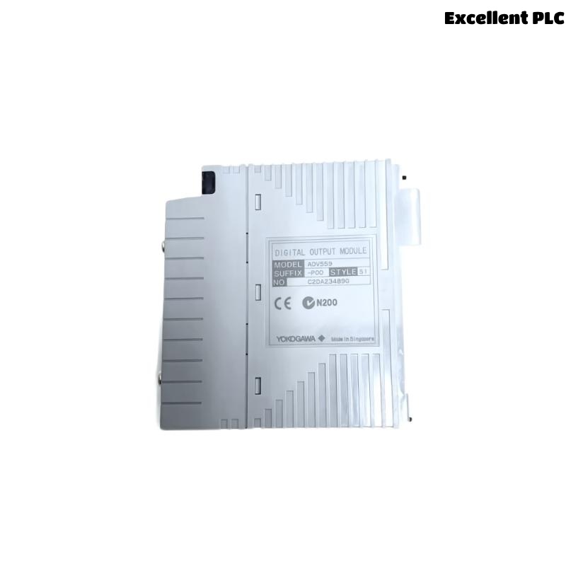
ADV559 Digital Output Module Overview
The Yokogawa ADV559 provides 32 isolated transistor output channels capable of switching 24 VDC field signals. The module is commonly installed in Yokogawa ESB Bus Node Units and compatible Field Control Units where reliable digital output control is required. It supports isolated channels, transistor contact outputs, configurable pulse-width functions, and response times of approximately 16 ms or less depending on system configuration.
Technical Features
- 32 isolated digital output channels
- 24 VDC transistor outputs
- Individual channel isolation
- Fast switching response
- Pulse width output capability
- Compatible with Yokogawa CENTUM platforms
Typical Industrial Applications
- Process valve control
- Motor starter control
- Relay switching
- Alarm annunciation
- Pump sequencing
- Interlock systems
Installation Planning
Before installation begins, verify engineering documentation and ensure that every output channel matches the approved I/O assignment.
- Review loop diagrams
- Verify cable schedules
- Check terminal numbering
- Prepare commissioning documents
- Confirm cabinet layout
Hardware Inspection
- Confirm module model number
- Inspect housing condition
- Verify connector integrity
- Inspect terminal assemblies
- Check retaining clips
Installation Environment
- Provide adequate ventilation
- Maintain clean cabinets
- Avoid excessive vibration
- Control humidity
- Separate signal and power cables
External Power Supply Verification
- Measure 24 VDC supply
- Verify polarity
- Inspect protection fuses
- Check voltage stability
- Verify common return conductors
Module Installation Procedure
- Switch off cabinet power.
- Insert the ADV559 module into the assigned slot.
- Lock the retaining mechanism securely.
- Connect the field terminal assembly.
- Inspect connector engagement.
- Restore system power.
ADV559 Wiring Installation Guide
Proper cable routing minimizes electromagnetic interference and simplifies future maintenance activities.
- Separate signal wiring from AC power cables
- Label every output channel
- Verify cable continuity
- Inspect insulation quality
- Confirm terminal torque
Grounding and Shielding
- Use single-point grounding
- Terminate cable shields correctly
- Avoid ground loops
- Verify cabinet bonding
- Measure grounding continuity
Controller Configuration
SCAN I/O MODULE
VERIFY NODE STATUS
ASSIGN OUTPUT CHANNELS
MAP PROCESS TAGS
DOWNLOAD CONFIGURATION
SAVE DATABASE
ENABLE OUTPUTS
Commissioning Procedure
- Issue manual output commands
- Measure output voltage
- Verify relay operation
- Observe field devices
- Record commissioning results
Functional Verification
- Confirm response time
- Inspect output LEDs
- Verify alarm outputs
- Review controller diagnostics
- Validate all output channels
Preventive Maintenance
- Inspect terminals every six months
- Measure output voltage periodically
- Review diagnostic logs
- Verify grounding annually
- Maintain project backups
Practical Commissioning Case
During startup of a petrochemical blending system, six solenoid valves connected to an ADV559 Digital Output Module failed to operate after commissioning.
Controller diagnostics reported normal operation, while the module produced a stable 24.1 VDC output. Electrical measurements at the valve terminals, however, showed only 11.2 VDC during switching.
Further investigation revealed a damaged common return conductor inside the marshalling cabinet that introduced excessive resistance into the output circuit.
After replacing the damaged wiring:
- All valves responded immediately.
- Output voltage recovered to normal operating values.
- No module replacement was required.
- The production line completed commissioning successfully.
Frequently Asked Questions
What types of equipment can the ADV559 control?
The module is suitable for relays, contactors, solenoid valves, alarm lamps, motor starters, and other 24 VDC discrete output devices.
Why should output wiring be separated from power cables?
Separating signal and power cables minimizes electrical interference, improves signal quality, and reduces the possibility of intermittent output faults.
What is the most important step before commissioning?
Verify all field wiring, controller configuration, external power supplies, and connected loads before energizing the system to ensure safe and reliable startup.
Summary: Successful installation of the Yokogawa ADV559 Digital Output Module depends on careful planning, correct field wiring, stable power supplies, effective grounding, and comprehensive commissioning procedures that verify every output channel under actual operating conditions.