

The Yokogawa AEP9D Secondary Power Supply Bus Unit is designed to distribute 24 VDC secondary power from Yokogawa PW601 or PW602 power supply units to Fieldbus power supplies, digital I/O modules, and other equipment installed within a CENTUM VP FIO cabinet. Supporting dual redundant power inputs and flexible output distribution, the AEP9D improves cabinet power reliability while simplifying power wiring. Proper installation, wiring, grounding, and commissioning are essential for ensuring stable secondary power distribution and continuous control system operation.
Contents
- 1. AEP9D Secondary Power Supply Bus Unit Overview
- 2. Technical Features
- 3. Typical Industrial Applications
- 4. Installation Planning
- 5. Hardware Inspection
- 6. Installation Environment
- 7. Bus Unit Mounting Procedure
- 8. Secondary Power Wiring
- 9. Grounding Requirements
- 10. Output Power Distribution
- 11. Wiring Verification
- 12. Commissioning Procedure
- 13. Functional Testing
- 14. Preventive Maintenance
- 15. Practical Installation Case
- 16. Frequently Asked Questions
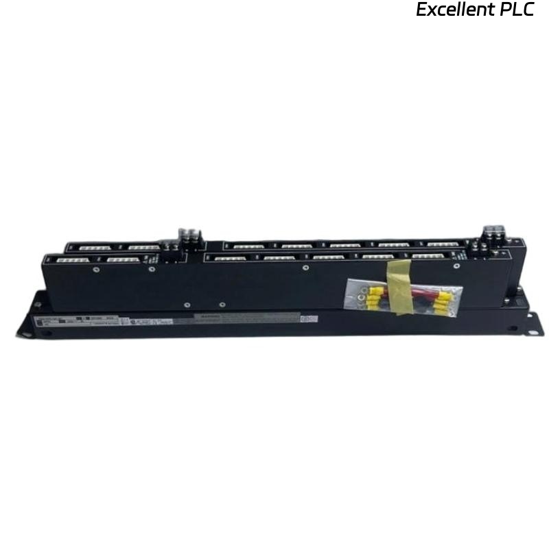
AEP9D Secondary Power Supply Bus Unit Overview
The AEP9D receives regulated 24 VDC power from Yokogawa PW601 or PW602 power supply units and distributes it throughout the control cabinet. The unit provides two independent input terminals (A and B), each supplying nine output ports. When the two input terminals are connected in parallel, one power source can supply all eighteen output ports. The unit supports a maximum input current of up to 30 A and a maximum output current of 10 A per port. It is specifically designed for Yokogawa CENTUM VP FIO systems.
Technical Features
- 24 VDC secondary power distribution
- Dual redundant power inputs
- Nine output ports for each input
- Eighteen outputs when inputs are paralleled
- Maximum input current up to 30 A
- Maximum output current of 10 A per port
Typical Industrial Applications
- CENTUM VP FIO cabinets
- Digital I/O power distribution
- Fieldbus power distribution
- Redundant cabinet power systems
- Oil and gas automation
- Chemical process control
Installation Planning
Proper planning helps ensure balanced power distribution and reliable cabinet operation.
- Review cabinet drawings
- Verify load calculations
- Confirm power supply capacity
- Prepare wiring schedules
- Inspect cabinet layout
Hardware Inspection
- Verify model number
- Inspect housing condition
- Check input connectors
- Inspect output connectors
- Verify mounting hardware
Installation Environment
- Maintain adequate ventilation
- Avoid excessive humidity
- Protect against vibration
- Prevent conductive dust accumulation
- Maintain cabinet cleanliness
Bus Unit Mounting Procedure
- Disconnect cabinet power.
- Install the AEP9D in the designated cabinet location.
- Secure the mounting hardware.
- Verify mechanical alignment.
- Inspect connector accessibility.
- Confirm adequate cable clearance.
Secondary Power Wiring
Secondary power wiring should follow approved engineering documentation and applicable electrical standards.
- Connect Input A from the power supply
- Connect Input B when redundancy is required
- Verify conductor polarity
- Tighten all connectors securely
- Label every power circuit
Grounding Requirements
- Connect functional ground correctly
- Verify cabinet bonding
- Maintain low earth resistance
- Avoid multiple grounding paths
- Inspect grounding continuity
Output Power Distribution
VERIFY 24 VDC INPUT
CONNECT INPUT A
CONNECT INPUT B
VERIFY OUTPUT PORTS
CHECK LOAD DISTRIBUTION
LABEL ALL POWER CIRCUITS
Wiring Verification
- Verify connector identification
- Confirm polarity
- Measure insulation resistance
- Review load allocation
- Verify engineering documentation
Commissioning Procedure
- Apply cabinet power
- Measure output voltage
- Verify redundant operation
- Inspect powered equipment
- Document commissioning results
Functional Testing
- Verify all output ports
- Measure voltage stability
- Test redundant input operation
- Monitor connected equipment
- Confirm proper cabinet operation
Preventive Maintenance
- Inspect connectors every six months
- Review load distribution annually
- Inspect grounding connections
- Clean cabinet interiors
- Maintain updated power distribution drawings
Practical Installation Case
During commissioning of a CENTUM VP cabinet, several digital I/O modules failed to power up even though the PW602 power supply indicated normal operation.
Inspection showed that the AEP9D received 24 VDC correctly at Input A, but one output connector supplying multiple digital modules had not been fully engaged during installation.
After reconnecting the output connector and verifying all eighteen output ports:
- All downstream digital modules powered up normally.
- Output voltage remained stable at every connector.
- Redundant power operation was successfully verified.
- The cabinet entered normal operation without replacing the AEP9D.
Frequently Asked Questions
What is the primary function of the AEP9D?
The AEP9D distributes regulated 24 VDC secondary power from PW601 or PW602 power supply units to Fieldbus power supplies, digital I/O modules, and other cabinet equipment.
How many output ports does the AEP9D provide?
The unit provides nine output ports for Input A and nine output ports for Input B. If the two inputs are connected in parallel, one power source can supply all eighteen output ports.
What are the maximum current ratings?
The AEP9D supports a maximum input current of 30 A and a maximum output current of 10 A per output port for 24 VDC power distribution.
Summary: Proper installation of the Yokogawa AEP9D Secondary Power Supply Bus Unit requires secure cabinet mounting, correct 24 VDC wiring, reliable grounding, balanced output distribution, and comprehensive commissioning to ensure dependable secondary power delivery for Yokogawa CENTUM VP FIO systems.