

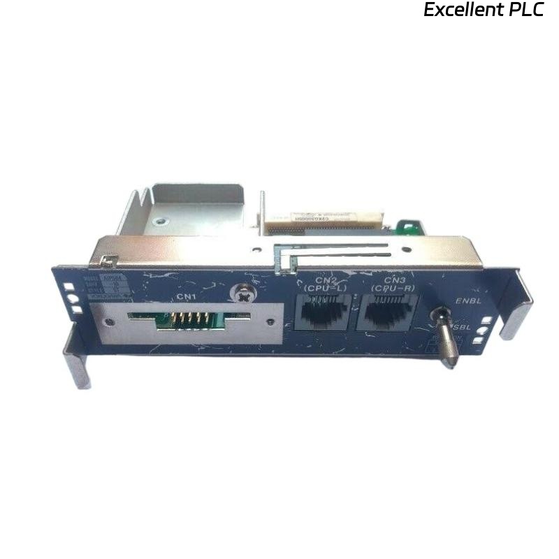
The Yokogawa AIP504-10 V-Net Coupler Unit is a communication interface module used in Yokogawa ProSafe-RS Safety Instrumented Systems (SIS) and CENTUM VP integrated control environments. It provides the communication interface between the Safety Control Station (SCS) processor module and the Yokogawa dual-redundant V-Net control network. The AIP504-10 performs signal isolation, signal level conversion, and deterministic data transmission while supporting redundant network communication to maximize system availability. Proper installation, wiring, switch configuration, and commissioning are essential to ensure safe and reliable operation in critical industrial applications.
Contents
- 1. Product Overview
- 2. Main Features
- 3. Typical Applications
- 4. Installation Preparation
- 5. Hardware Inspection
- 6. Module Installation
- 7. Processor and V-Net Cable Connections
- 8. Communication Switch Configuration
- 9. Commissioning Procedure
- 10. Functional Verification
- 11. Redundancy Verification
- 12. Preventive Maintenance
- 13. Practical Installation Case
- 14. Frequently Asked Questions
Product Overview
The AIP504-10 connects the Safety Control Station processor to the Yokogawa V-Net network through dedicated communication cables. In redundant systems, two AIP504-10 units are typically installed to provide independent communication paths for Bus 1 and Bus 2, ensuring continuous controller communication even if one network path becomes unavailable.
Main Features
- Dedicated V-Net communication interface
- Dual-redundant network support
- Signal isolation and level conversion
- Industrial-grade reliability for safety systems
- High-speed deterministic communication
- Status LED indicators for diagnostics
- Simple modular installation
- Designed for continuous 24/7 operation
Typical Applications
- ProSafe-RS Safety Control Stations (SCS)
- CENTUM VP integrated safety systems
- Emergency Shutdown Systems (ESD)
- Burner Management Systems (BMS)
- Oil and gas processing facilities
- Petrochemical and chemical plants
Installation Preparation
- Review approved network architecture drawings.
- Verify module compatibility with the processor.
- Prepare ESD protection equipment.
- Confirm V-Net branch cable availability.
- Ensure the maintenance procedure has been approved.
Hardware Inspection
- Verify the module model and revision.
- Inspect the housing for mechanical damage.
- Check processor interface connectors.
- Inspect V-Net branch connectors.
- Verify communication switch movement.
Module Installation
- Place the Safety Control Station in a maintenance state.
- Disconnect power if required by site procedures.
- Wear an approved anti-static wrist strap.
- Insert the AIP504-10 into its designated slot.
- Secure the retaining screws.
- Verify complete module engagement.
Processor and V-Net Cable Connections
- Connect the processor interface cable securely.
- Connect the V-Net branch connector.
- Verify cable locking mechanisms.
- Route communication cables separately from power wiring.
- Install the redundant Bus 2 connection if applicable.
Communication Switch Configuration
- Keep the communication switch in DSBL during installation.
- After completing all wiring, move the switch to ENBL.
- Verify both redundant couplers are enabled before startup.
- Confirm switch position during final inspection.
Commissioning Procedure
VERIFY INSTALLATION
CHECK ALL CABLE CONNECTIONS
SET SWITCH TO ENBL
POWER THE SYSTEM
VERIFY PROCESSOR DETECTION
VERIFY V-NET COMMUNICATION
TEST REDUNDANT NETWORK
START NORMAL OPERATION
Functional Verification
- Verify processor communication with V-Net.
- Confirm controller visibility from engineering stations.
- Check operator station connectivity.
- Review communication status LEDs.
- Verify absence of network alarms.
Redundancy Verification
- Test Bus 1 communication.
- Test Bus 2 communication.
- Simulate a single network path failure.
- Verify automatic communication switchover.
- Confirm uninterrupted controller operation.
Preventive Maintenance
- Inspect connectors during scheduled maintenance.
- Verify communication switch positions.
- Clean communication interfaces.
- Review network diagnostic logs.
- Perform periodic redundancy testing.
Practical Installation Case
During the commissioning of a new Safety Instrumented System, two AIP504-10 modules were installed to provide redundant V-Net communication for the Safety Control Station.
Initial startup reported communication alarms because the Bus 2 branch connector had not been fully secured.
After reconnecting the branch cable:
- Both communication buses became operational.
- The processor synchronized successfully with the V-Net.
- Engineering and operator stations established stable communication.
- The Safety Control Station completed commissioning without further communication alarms.
Frequently Asked Questions
What is the primary function of the AIP504-10?
The AIP504-10 provides the communication interface between the Safety Control Station processor and the Yokogawa dual-redundant V-Net control network while performing signal isolation and level conversion.
Why are two AIP504-10 units often installed?
Two modules support Bus 1 and Bus 2 redundant communication paths, ensuring continuous controller communication if one network path becomes unavailable.
What should be verified before commissioning?
Verify secure module installation, processor cable connections, V-Net branch cable connections, ENBL switch position, successful controller communication, and proper redundant network operation.
Summary
Proper installation of the Yokogawa AIP504-10 V-Net Coupler Unit requires secure module mounting, correct processor and V-Net cable connections, proper ENBL switch configuration, comprehensive communication testing, and redundancy verification. Following these procedures ensures reliable V-Net communication, high system availability, and safe operation in Yokogawa ProSafe-RS and CENTUM VP environments.