

Table of Contents
- Bently Nevada 170133-090-00 Installation Guide Entry
- Functional Role of Dual Proximitor Module in 3300 Systems
- Engineering Design Considerations for Dual Channels
- Rack Installation and Backplane Engagement
- Signal Conditioning and Calibration Alignment
- System Commissioning and Channel Verification
- FAQ
- Technical Summary
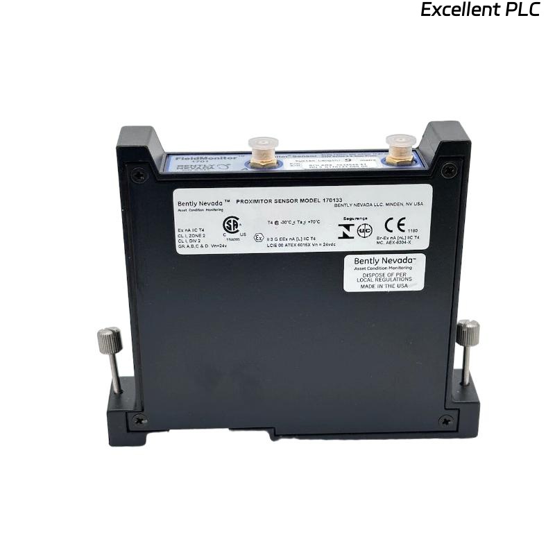
Bently Nevada 170133-090-00 Installation Guide Entry
Bently Nevada 170133-090-00 3300 internal dual proximitor module installation issues commonly result in channel inconsistency and signal distortion due to improper calibration alignment or incorrect probe system matching rather than module defects.
This Installation Guide emphasizes precise dual-channel setup and accurate signal conditioning for reliable vibration monitoring.
Functional Role of Dual Proximitor Module in 3300 Systems
- Processes signals from two independent proximity probe systems
- Provides conditioned voltage outputs for monitoring modules
- Supports differential and redundant vibration measurement strategies
Dual-channel integrity is essential for advanced machinery diagnostics.
Engineering Design Considerations for Dual Channels
- Use identical probe system lengths for both channels
- Ensure consistent probe gap settings across channels
- Avoid cross-channel interference through proper cable routing
- Maintain stable environmental conditions inside rack
Field Insight: Even small differences in probe gap (0.5V variation) can cause misleading trend comparisons.
Rack Installation and Backplane Engagement
- Power down 3300 rack before insertion
- Insert module into designated slot with correct orientation
- Ensure connectors fully engage with backplane
- Secure module to prevent vibration-induced loosening
Improper seating may lead to intermittent signal loss.
Signal Conditioning and Calibration Alignment
- Verify calibration matches probe system length (e.g., 5m, 7m)
- Adjust probe gaps to achieve consistent voltage range (-8V to -10V)
- Check output signal linearity for both channels
IF channels show offset:
    compare probe gap voltages
    adjust for consistency

IF signal nonlinear:
    verify calibration match
    check probe condition

IF no output:
    inspect backplane connection
    verify power supply
Real Case:
In a gas turbine system, Channel A showed 4 mm/s while Channel B indicated 6.5 mm/s under identical conditions. Gap voltage check revealed Channel B at -7V versus Channel A at -9V. After adjusting the gap, both channels aligned at ~4.2 mm/s.
System Commissioning and Channel Verification
- Measure output voltage from both channels under static and dynamic conditions
- Verify consistency between channels during machine startup
- Compare readings with baseline vibration signatures
Proper commissioning ensures dual-channel accuracy.
FAQ
Why are dual channels not matching?
This is usually due to differences in probe gap or calibration mismatch.
Can installation affect signal conditioning?
Yes, improper backplane connection or mounting affects signal stability.
How to ensure consistent channel output?
Use identical probe systems and carefully adjust probe gaps.
Technical Summary
This Installation Guide demonstrates that Bently Nevada 170133-090-00 dual proximitor module performance depends on accurate installation, consistent calibration, and proper system configuration. Precision setup ensures reliable dual-channel vibration monitoring.