

Table of Contents
- Bently Nevada 18622-010-01 Installation Guide Entry
- 18622-010-01 Cable Role in PLC / Monitoring Systems
- Cable Routing and Signal Integrity Strategy
- Physical Installation and Connection Method
- Installation Risks and Field Failures
- Commissioning and Signal Validation
- FAQ
- Technical Summary
Bently Nevada 18622-010-01 Installation Guide Entry
Bently Nevada 18622-010-01 interconnect cable installation failures are most often caused by improper routing and shielding errors, leading to signal interference rather than cable defects.
This Installation Guide focuses on maintaining signal integrity in vibration monitoring and PLC system communication.
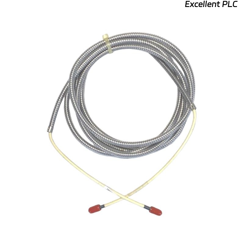
18622-010-01 Cable Role in PLC / Monitoring Systems
- Acts as signal transmission link between sensors, modules, and monitoring systems
- Supports vibration and condition monitoring systems (e.g., proximity or seismic systems)
- Ensures low-noise, high-integrity data transfer
- Typically armored with Teflon insulation for harsh environments
The cable is designed with high-quality copper conductors and shielding to minimize signal loss and EMI interference in industrial systems. :contentReference[oaicite:0]{index=0}
Cable Routing and Signal Integrity Strategy
Signal quality depends more on routing than on the cable itself:
- Separate signal cables from power cables (minimum 300 mm distance)
- Avoid parallel routing with high-voltage lines
- Use grounded cable trays where possible
- Maintain continuous shielding along the path
IF signal noisy:
    check cable proximity to power lines

IF intermittent signal:
    inspect connector termination

IF signal drift:
    verify grounding integrity
Engineering Insight: EMI is the primary failure mechanism in interconnect cables, not conductor damage.
Physical Installation and Connection Method
- Verify connector compatibility before installation
- Ensure tight and secure termination
- Avoid sharp bending (minimum bending radius)
- Protect cable armor from mechanical damage
The cable typically features armored protection and high-temperature insulation, allowing operation in -40°C to +150°C environments. :contentReference[oaicite:1]{index=1}
IF no signal:
    check connector seating

IF signal weak:
    inspect cable continuity

IF unstable:
    check shielding connection
Installation Risks and Field Failures
- Improper shielding termination
- Routing near high-voltage equipment
- Mechanical stress or cable bending
- Connector loosening over time
Real Case:
In a gas compressor station, vibration signal fluctuated randomly between 5–18 mA.
Observed Data:
- Noise spikes correlated with motor startup
Root Cause: Cable routed parallel to 6 kV motor power cable.
Solution:
- Re-routed cable with proper separation
- Improved shielding grounding
Result: Signal stabilized within 8–12 mA range.
Commissioning and Signal Validation
- Perform loop continuity test
- Check shielding grounding resistance
- Validate signal stability during equipment startup
Commissioning Tip: Always test under real operating conditions, not just idle state.
FAQ
What is the standard length of this cable?
The “010” option typically represents 10 ft (approx. 3 meters). :contentReference[oaicite:2]{index=2}
Why is signal noisy after installation?
This is usually due to improper routing near power cables or poor shielding grounding.
Can this cable be used in high-temperature environments?
Yes, it uses Teflon insulation and can operate in harsh industrial conditions. :contentReference[oaicite:3]{index=3}
Technical Summary
This Installation Guide shows that Bently Nevada 18622-010-01 performance depends on proper routing, shielding, and installation practices. Correct cable management ensures stable and interference-free signal transmission in industrial monitoring systems.