

Table of Contents
- Bently Nevada 18745-01 Installation Guide Entry
- 18745-01 Proximitor Sensor Role in Monitoring Systems
- System Matching Logic (Probe + Cable + Proximitor)
- Installation and Wiring Configuration
- Installation Risks and Engineering Pitfalls
- Commissioning and Gap Voltage Validation
- FAQ
- Technical Summary
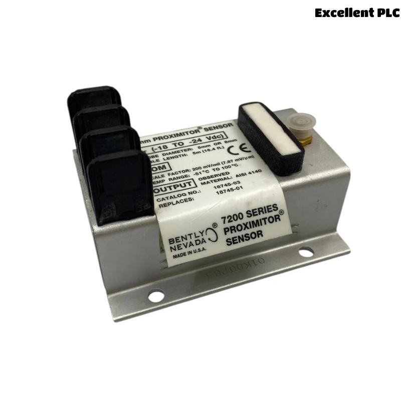
Bently Nevada 18745-01 Installation Guide Entry
Bently Nevada 18745-01 Proximitor sensor installation failures are most commonly caused by incorrect system length matching (probe + extension cable + Proximitor), leading to nonlinear output rather than sensor malfunction.
This Installation Guide focuses on proper setup of 7200 series proximity transducer systems used in shaft vibration and position monitoring.
18745-01 Proximitor Sensor Role in Monitoring Systems
- Converts probe gap into voltage signal (gap-to-voltage)
- Provides signal conditioning for proximity probes
- Outputs dynamic vibration and static position signals
- Interfaces with PLC, DCS, and Bently Nevada 3300 systems
The 7200 series is a non-contact measurement system widely used for rotating machinery diagnostics. :contentReference[oaicite:1]{index=1}
System Matching Logic (Probe + Cable + Proximitor)
Installation must follow strict system matching rules:
- Total system length must be 5 m or 9 m
- Probe, extension cable, and Proximitor must match
- Incorrect combination leads to scaling and linearity errors
IF gap voltage abnormal:
    check system length mismatch

IF vibration reading incorrect:
    verify probe compatibility

IF signal nonlinear:
    mismatch between components
Engineering Insight: Proximitor does not measure directly—it conditions the signal. Any mismatch breaks calibration.
Installation and Wiring Configuration
Mechanical Setup
- Mount Proximitor in junction box or control panel
- Ensure proper ventilation and temperature control
Electrical Wiring
- Power supply: typically -24 VDC
- Connect probe and extension cable securely
- Use shielded cable with single-point grounding
IF no output:
    check power supply (-24V)

IF signal noisy:
    verify shielding and grounding

IF signal unstable:
    inspect connectors
Installation Risks and Engineering Pitfalls
- Incorrect system length (5 m vs 9 m mismatch)
- Improper probe installation (gap outside linear range)
- Poor grounding causing noise
- Using incompatible 3300/3500 system components
Real Case:
During a turbine retrofit, vibration readings doubled after replacing the Proximitor.
Observed Data:
- Output increased from 200 mV/mil to ~400 mV/mil
Root Cause: Wrong Proximitor matched with probe/cable.
Solution:
- Installed correct 5 m matched system
Result: Signal returned to calibrated range.
Commissioning and Gap Voltage Validation
- Measure gap voltage (-8 V to -12 V typical)
- Verify linear response during shaft rotation
- Compare with reference vibration analyzer
Commissioning Tip: Always set probe gap at mid-linear range before operation.
FAQ
What is the function of the Proximitor sensor?
It converts probe gap into a usable voltage signal for monitoring systems.
Why is system matching important?
Mismatch causes scaling errors and inaccurate vibration readings.
Can it be used with modern systems?
It is mainly compatible with legacy 7200 and 3300 systems.
Technical Summary
This Installation Guide shows that Bently Nevada 18745-01 performance depends on strict system matching, correct wiring, and proper gap setup. Accurate installation ensures reliable shaft vibration and position monitoring.