

Table of Contents
- 200200-05-05 Fault Diagnosis Entry
- Common Symptoms of 200200-05-05 Module Fault
- Fault Diagnosis Process
- Common Causes of Dual Input Module Fault
- Diagnostic Methods and Tools
- Corrective Actions and Recovery
- Real Troubleshooting Case
- Troubleshooting FAQ
- Final Technical Summary
200200-05-05 Fault Diagnosis Entry
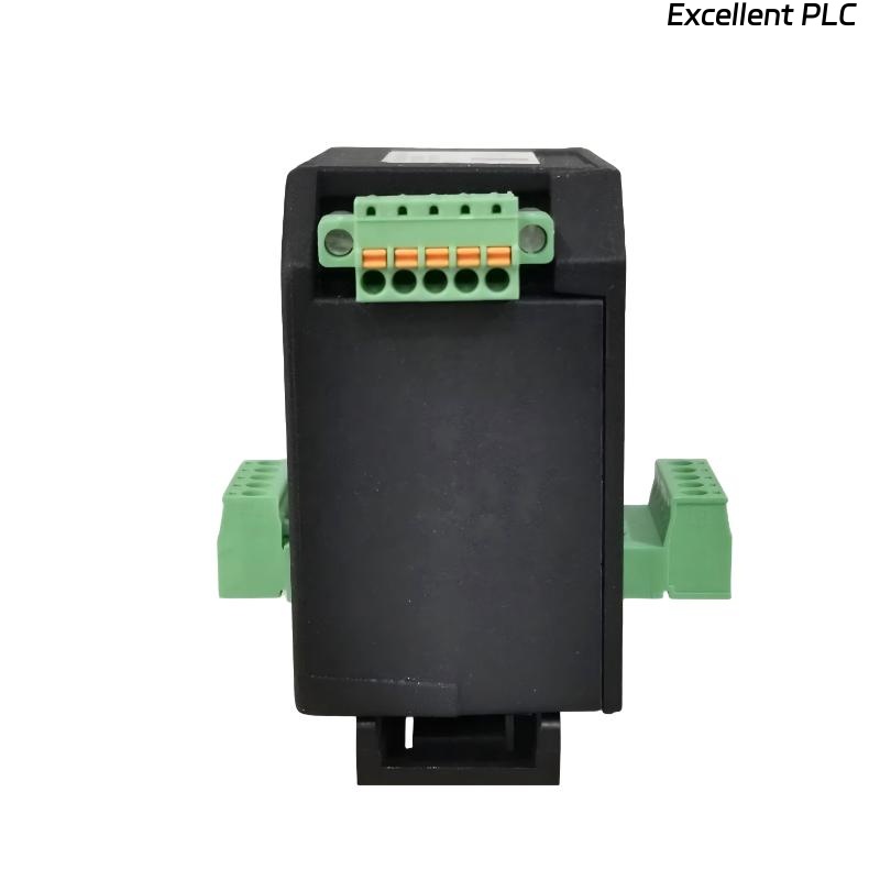
The Bently Nevada 200200-05-05 Trendmaster proTim-R dual input module can experience issues such as signal loss, noise, or instability in the vibration data from either or both input channels. These issues are commonly caused by wiring problems, incorrect configurations, or electromagnetic interference (EMI).
Common Symptoms of 200200-05-05 Module Fault
- Signal dropouts or intermittent signal loss from one or both input channels
- Erratic readings or noise in the signal during machine startup or under load
- Alarm triggers even when the machine is operating normally
- Discrepancy between signals from the two input channels
Fault Diagnosis Process
To diagnose faults with the Bently Nevada 200200-05-05 module, follow these steps to pinpoint the root cause:
- Check all wiring connections for loose or damaged connections
- Verify that both input channels are correctly configured in the Trendmaster software
- Inspect the physical condition of the module and connected sensors for any visible damage or wear
- Test for electromagnetic interference (EMI) using an oscilloscope to check for signal noise
- Examine the grounding of the module and sensor cables to ensure proper shielding
  // Fault Diagnosis Logic
  IF Signal_Loss THEN
      Inspect_Wiring_And_Connector_Integrity();
      Verify_Grounding_And_Shielding();
  ELSEIF Signal_Variability THEN
      Check_Sensor_Configuration_And_Calibration();
  ELSE
      Confirm_Configuration_Settings();
  END_IF;
Common Causes of Dual Input Module Fault
- Loose or disconnected wiring between the module and sensors
- Electromagnetic interference (EMI) from nearby electrical equipment or high-power cables
- Improper grounding or inadequate shielding of cables and input channels
- Incorrect sensor configuration settings in the Trendmaster software
- Physical damage to the module or connectors, affecting signal transmission
Diagnostic Methods and Tools
- Multimeter for verifying continuity and checking for wiring issues
- Oscilloscope to detect noise or fluctuations in the signal
- Vibration analysis equipment to cross-check sensor outputs with actual machine behavior
- Electromagnetic field (EMF) tester to detect potential EMI sources near the installation
Corrective Actions and Recovery
- Replace or repair any damaged wiring or connectors
- Reroute cables to avoid sources of EMI, ensuring they are as short as possible and properly shielded
- Ensure that both the module and sensor wiring are adequately grounded to reduce electrical noise
- Reconfigure the sensor settings in the Trendmaster software to match the operational parameters of the system
- Calibrate sensors to ensure accurate readings and proper signal output
Real Troubleshooting Case
During a field installation of the 200200-05-05 module in a pump monitoring system, intermittent signal dropouts were observed:
- The signal from one input channel would frequently disappear when the system underwent startup cycles
- Investigation revealed that the cable for the affected sensor was routed near high-voltage power lines, causing EMI interference
After rerouting the cable away from the high-voltage lines and ensuring proper shielding, the system’s signal became stable:
- The signal output from both channels remained consistent during all operating conditions
- Subsequent calibration and configuration adjustments ensured that the monitoring system operated without false alarms
Troubleshooting FAQ
What should I do if my signal drops intermittently?
Intermittent signal loss is often caused by loose connections, EMI, or wiring damage. Check all connections and ensure cables are shielded and grounded properly. Reroute any cables near sources of interference.
How can I identify if EMI is affecting my system?
Use an oscilloscope to check the signals for noise or fluctuations. Also, inspect the environment for high-voltage cables or equipment that could be emitting electromagnetic fields. EMF testers can also help identify sources of EMI.
Why are my sensor readings inconsistent between the two input channels?
Inconsistent readings may be due to incorrect sensor calibration, improper wiring, or signal interference. Verify that both sensors are correctly configured in the system, and check for any wiring or grounding issues.
Final Technical Summary
The Bently Nevada 200200-05-05 Trendmaster proTim-R Dual Input Module Troubleshooting Guide provides a systematic approach to identifying and resolving signal-related issues. Ensuring that the wiring is intact, the module is properly configured, and the system is shielded from EMI is crucial for maintaining stable performance. By following these troubleshooting steps, you can maximize the reliability and accuracy of your vibration monitoring system, ensuring continuous operation of critical machinery.