 Excellent PLC


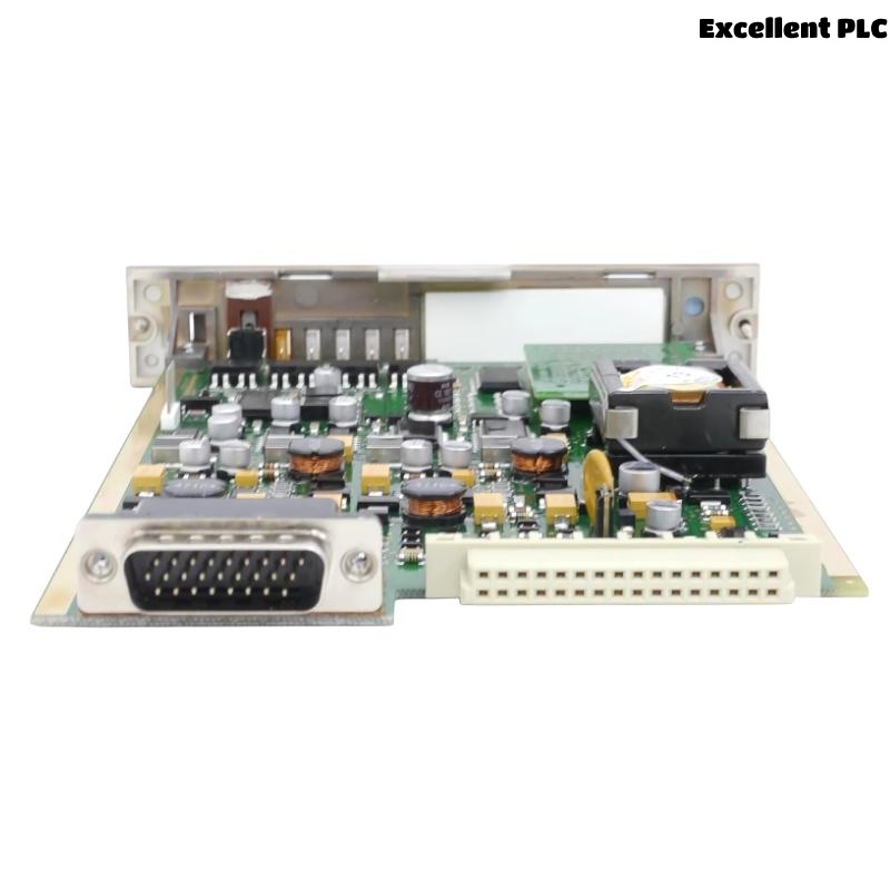
The Honeywell 05704-A-0144 Four Channel Control Card is a microprocessor-based controller module for the Honeywell System 5704 Gas Detection Controller. It monitors up to four catalytic combustible gas detectors while providing alarm processing, LCD indication, fault monitoring, remote reset, remote inhibit, and optional analog output functions. During long-term operation, faults such as detector communication failures, alarm malfunctions, calibration drift, wiring problems, or analog output abnormalities may affect system performance. A structured troubleshooting procedure helps maintenance engineers quickly identify the root cause and restore reliable gas detection.
Contents
- 1. Understanding Control Card Faults
- 2. Common Failure Symptoms
- 3. Typical Causes
- 4. Initial Hardware Inspection
- 5. Electrical Verification
- 6. Diagnostic Analysis
- 7. Recommended Troubleshooting Workflow
- 8. Corrective Actions
- 9. Functional Recovery Verification
- 10. Preventive Maintenance
- 11. Industrial Maintenance Case
- 12. Frequently Asked Questions
Understanding Control Card Faults
The Honeywell 05704-A-0144 continuously receives signals from catalytic gas detectors, processes gas concentration values, activates alarm outputs, and transmits information to external monitoring systems. Problems may be caused by sensor failures, damaged field wiring, incorrect calibration, unstable power supplies, communication faults, or internal control card failures. Prompt diagnosis is essential to maintain continuous combustible gas monitoring.
Common Failure Symptoms
- One or more detector channels display fault status.
- Gas concentration remains fixed at zero or full scale.
- False gas alarms occur without gas exposure.
- A1, A2, or A3 alarms fail to activate.
- LCD display shows communication or channel errors.
- Analog output is unstable or unavailable.
- Remote reset function does not operate.
- Controller continuously reports detector faults.
Typical Causes
- Catalytic detector failure.
- Open circuit or short circuit in field wiring.
- Incorrect detector calibration.
- Loose terminal connections.
- Power supply instability.
- Incorrect alarm configuration.
- Analog output module malfunction.
- Internal control card hardware failure.
Initial Hardware Inspection
- Verify controller power supply.
- Inspect detector wiring terminals.
- Check module installation.
- Inspect detector connectors.
- Verify LCD status indicators.
- Review controller diagnostic messages.
Electrical Verification
- Measure detector supply voltage.
- Verify sensor loop continuity.
- Measure detector output signals.
- Inspect cable insulation resistance.
- Verify analog output current if installed.
- Check protective grounding.
Diagnostic Analysis
| Observed Condition | Possible Diagnosis |
|---|---|
| Detector channel fault | Sensor failure, wiring fault, or channel hardware problem |
| No gas reading | Open detector circuit or failed catalytic sensor |
| False alarm activation | Calibration drift, electrical noise, or incorrect alarm settings |
| No alarm output | Relay configuration error or output hardware fault |
| Analog output abnormal | Optional output module failure or incorrect configuration |
Recommended Troubleshooting Workflow
VERIFY SYSTEM POWER
CHECK DETECTOR STATUS
INSPECT FIELD WIRING
VERIFY SENSOR CALIBRATION
TEST ALARM FUNCTIONS
CHECK ANALOG OUTPUTS
VERIFY CONFIGURATION
CONFIRM NORMAL OPERATION
Corrective Actions
- Replace defective catalytic gas detectors.
- Repair damaged field wiring.
- Tighten loose terminal connections.
- Perform detector recalibration.
- Correct alarm configuration parameters.
- Replace faulty analog output modules if installed.
- Clean module connectors.
- Replace the control card after confirming internal hardware failure.
Functional Recovery Verification
- Verify all four detector channels operate normally.
- Confirm accurate gas concentration readings.
- Test A1, A2, and A3 alarm functions.
- Verify LCD status indications.
- Confirm analog output accuracy.
- Monitor long-term operational stability.
Preventive Maintenance
- Calibrate detectors according to maintenance schedules.
- Inspect detector wiring regularly.
- Clean module connectors.
- Verify alarm thresholds.
- Inspect analog outputs periodically.
- Maintain detailed calibration records.
Industrial Maintenance Case
During a scheduled inspection at a petrochemical facility, Channel 2 of a Honeywell 05704-A-0144 Four Channel Control Card continuously reported a fault and failed to detect combustible gas during calibration testing. Engineers discovered corrosion on the detector terminal block combined with calibration drift in the catalytic sensor.
After cleaning the terminals, replacing the detector, recalibrating the sensing channel, verifying alarm thresholds, and repeating functional testing:
- All four channels measured gas concentrations accurately.
- A1, A2, and A3 alarms activated correctly.
- Analog outputs matched calibration values.
- The System 5704 controller resumed stable operation without additional channel faults.
Frequently Asked Questions
Why does one detector channel remain in fault condition?
The most common causes are a failed catalytic detector, damaged field wiring, loose terminal connections, incorrect calibration, or a channel hardware fault on the control card.
Why is the gas concentration reading unstable?
Unstable readings are typically caused by detector aging, electrical interference, calibration errors, unstable power supplies, or poor wiring connections.
When should the Honeywell 05704-A-0144 Four Channel Control Card be replaced?
The module should be replaced only after verifying that the detectors, field wiring, power supply, alarm configuration, analog output modules, and calibration are functioning correctly while the control card continues to exhibit internal hardware or communication failures.
Summary
Effective troubleshooting of the Honeywell 05704-A-0144 Four Channel Control Card requires systematic inspection of detector channels, field wiring, calibration status, alarm outputs, analog signals, and controller diagnostics. Routine preventive maintenance and scheduled calibration help ensure reliable combustible gas monitoring and long-term operational safety in Honeywell System 5704 gas detection systems.