

Yokogawa ADV151-E63 Digital Input Module installation failures are typically caused by incorrect field wiring, unsuitable grounding, or incomplete System Configuration rather than actual hardware defects. Following a structured Installation Guide helps engineers complete Setup and Commissioning efficiently while ensuring stable digital signal acquisition throughout the control system lifecycle.
Contents
- ADV151-E63 Digital Input Module Overview
- ADV151-E63 Role in Control Systems
- ADV151-E63 Installation Planning
- ADV151-E63 Pre-Installation Checklist
- ADV151-E63 Installation Environment Requirements
- ADV151-E63 Power and Signal Requirements
- ADV151-E63 Wiring Strategy
- ADV151-E63 Grounding Recommendations
- ADV151-E63 Module Mounting Procedure
- ADV151-E63 System Configuration Setup
- ADV151-E63 Input Verification
- ADV151-E63 Commissioning Workflow
- ADV151-E63 Signal Optimization
- ADV151-E63 Maintenance Practices
- Real Commissioning Experience
- FAQ
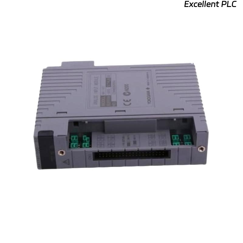
ADV151-E63 Digital Input Module Overview
The Yokogawa ADV151-E63 Digital Input Module is designed for reliable acquisition of digital field signals from switches, relays, limit switches, valve feedback contacts, and process interlock devices. It is commonly deployed in distributed control systems where accurate status monitoring is critical.
ADV151-E63 Role in Control Systems
- Equipment status monitoring
- Process interlock supervision
- Alarm signal acquisition
- Shutdown sequence monitoring
- Operator interface feedback
ADV151-E63 Installation Planning
Successful installation begins with engineering preparation. Before mounting the module, review signal allocation drawings, cabinet layouts, terminal schedules, and control narratives.
- Confirm I/O database assignments
- Verify cabinet slot allocation
- Review signal loop drawings
- Check spare channel availability
- Validate controller compatibility
ADV151-E63 Pre-Installation Checklist
- Module model verified
- Terminal blocks inspected
- Cabinet power isolated
- Wiring drawings available
- Commissioning procedures approved
ADV151-E63 Installation Environment Requirements
- Temperature stability
- Low humidity levels
- Adequate ventilation
- Minimal vibration exposure
- Reliable grounding network
ADV151-E63 Power and Signal Requirements
Prior to Setup, engineers should verify all digital signals and power references.
- 24 VDC signal verification
- Polarity confirmation
- Common return validation
- Ground continuity inspection
- Noise source identification
ADV151-E63 Wiring Strategy
- Separate signal and power cables
- Use labeled conductors
- Avoid parallel routing with motor feeders
- Maintain shielding continuity
- Verify terminal torque values
ADV151-E63 Grounding Recommendations
Field experience shows that unstable digital inputs are frequently caused by poor grounding rather than module faults.
- Use a single-point grounding philosophy
- Avoid multiple ground loops
- Inspect cabinet grounding bars
- Measure grounding resistance
ADV151-E63 Module Mounting Procedure
- Isolate system power.
- Insert ADV151-E63 into the designated slot.
- Secure locking mechanisms.
- Connect terminal assemblies.
- Verify mechanical installation.
- Restore cabinet power.
- Observe diagnostic indicators.
ADV151-E63 System Configuration Setup
INSTALL MODULE
POWER ON SYSTEM
DETECT MODULE
ASSIGN INPUT CHANNELS
DOWNLOAD DATABASE
VERIFY TAG MAPPING
SAVE CONFIGURATION
START COMMISSIONING
ADV151-E63 Input Verification
- Check channel response
- Verify alarm operation
- Confirm event recording
- Validate HMI indications
- Review controller diagnostics
ADV151-E63 Commissioning Workflow
Commissioning should include both simulation and live signal testing. Engineers should verify actual field devices instead of relying solely on software forcing.
- Activate field contacts
- Observe controller response
- Verify alarm annunciation
- Record commissioning results
ADV151-E63 Signal Optimization
- Improve shielding quality
- Reduce electromagnetic interference
- Separate high-current circuits
- Monitor signal stability trends
ADV151-E63 Maintenance Practices
- Inspect terminals annually
- Review diagnostic records
- Check grounding integrity
- Maintain configuration backups
Real Commissioning Experience
During startup of a wastewater treatment facility, engineers found that nine ADV151-E63 channels remained inactive even though field limit switches were operating correctly.
- Input Voltage: 24.1 VDC
- Controller Status: Normal
- Module Status: Healthy
- Inactive Inputs: 9
After tracing the wiring route, engineers discovered that a marshalling panel common return conductor had been terminated on the wrong terminal strip.
Following correction:
- All channels became operational
- Alarm testing passed
- Control logic executed correctly
- Commissioning completed successfully
In one commissioning case, wiring verification prevented unnecessary module replacement and reduced startup delays.
ADV151-E63 Installation Guide FAQ
What signals can the ADV151-E63 monitor?
The module monitors digital ON/OFF signals from switches, relays, sensors, valve feedback devices, and process equipment contacts.
Why is System Configuration verification important?
Incorrect channel mapping may cause false alarms, incorrect operator displays, and improper control actions.
What is the most common installation problem?
Field wiring errors and grounding deficiencies are more common than actual Digital Input Module failures.
Summary: Reliable ADV151-E63 Installation, Setup, and Commissioning require proper wiring practices, validated System Configuration, effective grounding, and comprehensive field verification.