

Yokogawa ADV551-E63 Digital Output Module installation problems are usually caused by incorrect field wiring, improper external power distribution, or inaccurate System Configuration rather than hardware defects. Following this Installation Guide helps engineers complete Setup and Commissioning efficiently while ensuring reliable output control for industrial automation systems.
Contents
- 1. Yokogawa ADV551-E63 Digital Output Module Overview
- 2. ADV551-E63 Module Features
- 3. Engineering Preparation
- 4. Hardware Inspection
- 5. Installation Environment
- 6. External Power Verification
- 7. Module Mounting Procedure
- 8. ADV551-E63 Wiring Installation Guide
- 9. Grounding and Shielding
- 10. System Configuration
- 11. Output Verification
- 12. Commissioning Procedure
- 13. Reliability Optimization
- 14. Preventive Maintenance
- 15. Real Commissioning Case
- 16. FAQ
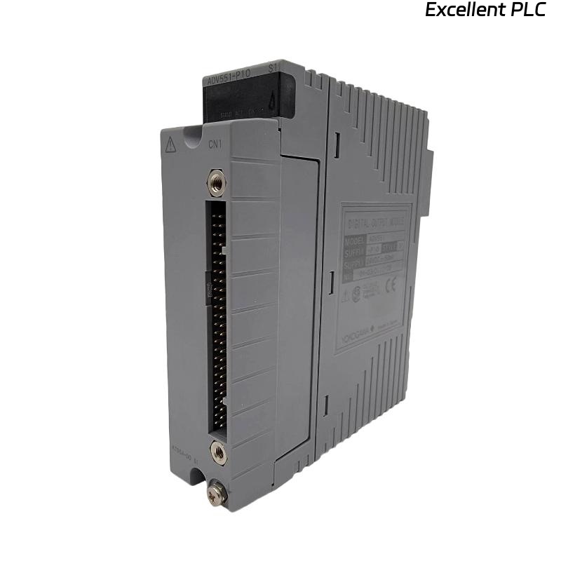
Yokogawa ADV551-E63 Digital Output Module Overview
The Yokogawa ADV551-E63 is a 32-channel isolated Digital Output Module designed for 24 VDC control systems. It provides current-sink transistor outputs and supports pulse-width and time-proportional output functions, making it suitable for controlling relays, solenoid valves, motor starters, alarm circuits, and other industrial field devices.
ADV551-E63 Module Features
- 32 isolated digital output channels
- 24 VDC transistor outputs
- Current sink output design
- High electrical isolation
- Fast output response
- Supports redundant control systems
Engineering Preparation
Installation begins with engineering verification rather than cabinet wiring. Confirm that every output channel corresponds to the latest I/O allocation drawing before connecting field devices.
- Verify loop diagrams
- Check terminal schedules
- Review cable numbers
- Confirm output assignment
- Prepare commissioning records
Hardware Inspection
- Verify module model
- Inspect housing condition
- Check connector alignment
- Inspect terminal blocks
- Confirm locking mechanism
Installation Environment
- Maintain clean ventilation
- Avoid excessive humidity
- Reduce vibration exposure
- Separate power cables from signal cables
- Ensure proper cabinet grounding
External Power Verification
- Measure 24 VDC supply
- Verify polarity
- Inspect protective fuses
- Check voltage stability
- Verify common return wiring
Module Mounting Procedure
- Disconnect cabinet power.
- Install the ADV551-E63 into the designated slot.
- Lock the retaining mechanism.
- Connect the terminal assembly.
- Verify mechanical engagement.
- Restore cabinet power.
ADV551-E63 Wiring Installation Guide
Correct field wiring minimizes future Troubleshooting and improves long-term output reliability.
- Separate output wiring from AC power cables
- Label every output circuit
- Verify terminal numbering
- Perform continuity testing
- Inspect insulation condition
Grounding and Shielding
- Use single-point grounding
- Terminate cable shields correctly
- Avoid ground loops
- Verify cabinet bonding
- Measure grounding continuity
System Configuration
SCAN MODULE
VERIFY NODE STATUS
ASSIGN OUTPUT CHANNELS
DOWNLOAD DATABASE
VERIFY TAGS
ENABLE OUTPUTS
SAVE CONFIGURATION
Output Verification
- Execute manual output commands
- Measure output voltage
- Observe relay operation
- Verify valve movement
- Check operator graphics
Commissioning Procedure
Commissioning should always include live field testing. Functional testing with actual loads verifies both the controller logic and field wiring integrity.
Reliability Optimization
- Improve cable routing
- Reduce electrical noise
- Optimize cabinet grounding
- Update wiring documentation
Preventive Maintenance
- Inspect terminals annually
- Verify output voltage
- Review controller diagnostics
- Maintain configuration backups
Real Commissioning Case
During commissioning of a chemical blending system, five solenoid valves controlled by an ADV551-E63 failed to operate after startup.
Measured output voltage at the module was 24.2 VDC, while voltage at the valve terminals dropped below 11 VDC under load.
We observed that a damaged terminal strip introduced excessive resistance into the output circuit.
After replacing the terminal strip:
- Valve response recovered immediately.
- Output voltage stabilized at 24 VDC.
- Commissioning completed without replacing the module.
- No further output alarms occurred during the following 72-hour reliability test.
ADV551-E63 Installation Guide FAQ
Which field devices are commonly controlled by the ADV551-E63?
The module is typically used for relays, contactors, solenoid valves, indicator lamps, alarm circuits, and process shutdown outputs.
Why is external power verification important?
Stable external power ensures that field devices receive sufficient operating voltage even when multiple outputs are energized simultaneously.
Can commissioning rely only on controller diagnostics?
No. Live functional testing confirms correct controller logic, wiring integrity, and actual field equipment response.
Summary: Successful ADV551-E63 Installation, Setup, and Commissioning depend on accurate wiring, reliable power distribution, proper grounding, and complete System Configuration before plant startup.