

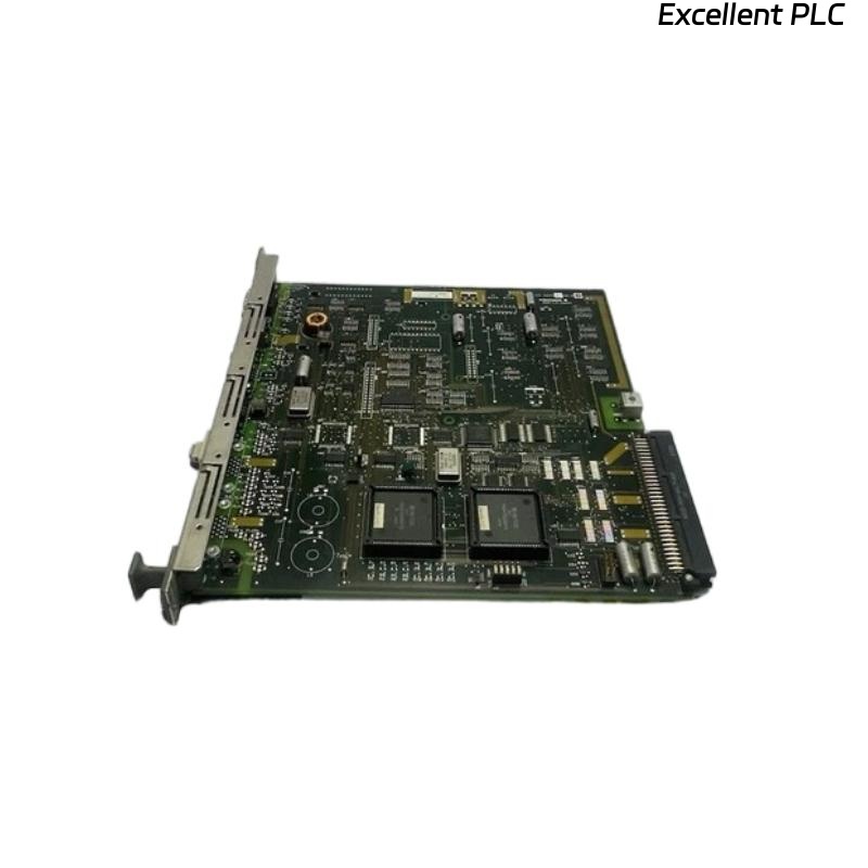
The Yokogawa AIP125 PLC Module Board is an industrial automation module equipped with integrated connectors, plugs, and terminal interfaces for reliable signal transmission and control system integration. Designed for use in Yokogawa Distributed Control Systems (DCS) and PLC-based automation platforms, the module board provides stable electrical connections between processors, I/O modules, communication networks, and field devices. Its compact modular design simplifies installation, reduces wiring complexity, and improves maintenance efficiency in demanding industrial environments. Proper installation, wiring, grounding, and commissioning are essential to ensure dependable communication, accurate signal transmission, and long-term operational reliability.
Contents
- 1. Product Overview
- 2. Main Features
- 3. Typical Applications
- 4. Installation Preparation
- 5. Hardware Inspection
- 6. Module Installation
- 7. Connector and Terminal Wiring
- 8. Power Connections
- 9. Grounding Requirements
- 10. Commissioning Procedure
- 11. Functional Testing
- 12. Preventive Maintenance
- 13. Practical Installation Case
- 14. Frequently Asked Questions
Product Overview
The AIP125 module board provides secure electrical interfaces through industrial-grade connectors, plugs, and terminal blocks. It facilitates communication and signal distribution between Yokogawa controllers, I/O modules, power supplies, and field instruments while ensuring stable electrical performance in industrial environments.
Main Features
- Industrial PLC module board design
- Integrated connectors and terminal interfaces
- Reliable signal transmission
- Compact modular construction
- High mechanical durability
- Easy installation and maintenance
- Supports industrial control system integration
- Designed for continuous operation
Typical Applications
- Distributed Control Systems (DCS)
- PLC automation systems
- Oil and gas facilities
- Chemical processing plants
- Power generation stations
- Water treatment automation
Installation Preparation
- Review system wiring drawings.
- Verify module compatibility.
- Prepare cabinet installation location.
- Inspect required communication cables.
- Confirm power availability.
Hardware Inspection
- Verify module model number.
- Inspect PCB for physical damage.
- Check connectors and plugs.
- Inspect terminal blocks.
- Verify supplied accessories.
Module Installation
- Disconnect cabinet power.
- Install the module into the designated slot.
- Secure all retaining hardware.
- Verify connector engagement.
- Inspect module alignment.
Connector and Terminal Wiring
- Connect field wiring according to engineering drawings.
- Verify terminal numbering.
- Tighten all terminal screws.
- Separate signal and power wiring.
- Label all cables clearly.
Power Connections
- Verify input voltage.
- Connect the specified power source.
- Inspect protective devices.
- Verify polarity before energizing.
- Confirm power indicators after startup.
Grounding Requirements
- Connect protective earth.
- Maintain low grounding resistance.
- Avoid ground loops.
- Verify cabinet grounding continuity.
- Inspect grounding periodically.
Commissioning Procedure
VERIFY INSTALLATION
VERIFY TERMINAL WIRING
CONNECT POWER
VERIFY GROUNDING
POWER UP MODULE
VERIFY COMMUNICATION
TEST SIGNALS
VALIDATE OPERATION
START NORMAL SERVICE
Functional Testing
- Verify module startup.
- Confirm communication status.
- Check field signal integrity.
- Verify terminal continuity.
- Review diagnostic information.
Preventive Maintenance
- Inspect connectors regularly.
- Retighten terminal screws if required.
- Clean dust from the module surface.
- Review diagnostic records.
- Maintain wiring documentation.
Practical Installation Case
During commissioning of a process control cabinet, several field input signals connected through an AIP125 module were unstable.
Inspection found that multiple terminal screws had not been tightened to the recommended torque during installation, resulting in intermittent electrical contact.
After securing the terminal connections:
- Signal stability was restored.
- Communication errors disappeared.
- Field devices operated normally.
- The control system entered reliable continuous operation.
Frequently Asked Questions
What is the primary function of the AIP125?
The AIP125 provides reliable electrical interfaces using integrated connectors, plugs, and terminal blocks for connecting controllers, I/O modules, and field devices within industrial automation systems.
Why is proper terminal tightening important?
Correct terminal torque ensures reliable electrical contact, minimizes voltage drops, and prevents intermittent signal faults caused by vibration or thermal cycling.
What should be checked before commissioning?
Verify module installation, connector engagement, terminal wiring, power connections, grounding, communication interfaces, and overall wiring integrity before energizing the system.
Summary
Proper installation of the Yokogawa AIP125 PLC Module Board requires careful hardware inspection, secure cabinet mounting, correct connector and terminal wiring, reliable power connections, effective grounding, and thorough commissioning. Following these procedures helps ensure stable signal transmission, dependable communication, simplified maintenance, and long-term industrial automation reliability.