

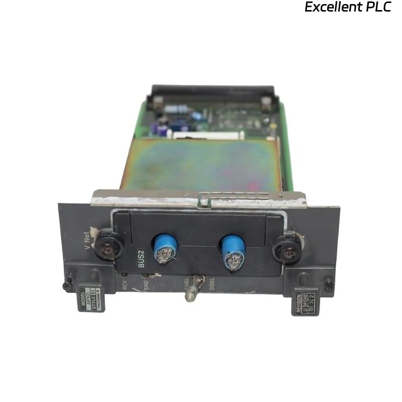
The Yokogawa AIP501 V Net Coupler Unit is a communication interface module used in Yokogawa CENTUM CS 3000 and CENTUM VP Distributed Control Systems (DCS). It provides the physical connection between the Field Control Unit (FCU) and the Yokogawa V net real-time control network, enabling deterministic, high-speed communication between controllers, operator stations, engineering stations, gateways, and other system components. The AIP501 supports redundant network configurations to improve system availability and operational reliability. Proper installation, cable routing, network configuration, and commissioning are essential to ensure stable communication and fault-tolerant network operation.
Contents
- 1. Product Overview
- 2. Main Features
- 3. Typical Applications
- 4. Installation Preparation
- 5. Hardware Inspection
- 6. V Net Coupler Installation
- 7. V Net Cable Connection
- 8. Network Configuration
- 9. Commissioning Procedure
- 10. Functional Testing
- 11. Preventive Maintenance
- 12. Practical Installation Case
- 13. Frequently Asked Questions
Product Overview
The AIP501 provides the communication interface between the FCU and the Yokogawa V net process control network. It enables reliable real-time data exchange between distributed controllers and supervisory systems while supporting redundant communication paths for high system availability.
Main Features
- Real-time V net communication interface
- Support for redundant network architecture
- High-speed deterministic communication
- Industrial-grade reliability
- Dual-channel communication capability
- Easy replacement and maintenance
- Backplane integration with FCU
- Continuous 24-hour industrial operation
Typical Applications
- CENTUM VP Field Control Units
- CENTUM CS 3000 controllers
- Process control networks
- Oil and gas facilities
- Power generation plants
- Petrochemical automation systems
Installation Preparation
- Review the network architecture.
- Verify V net cable routing.
- Confirm compatible controller configuration.
- Prepare anti-static protection.
- Ensure redundant communication paths are available if required.
Hardware Inspection
- Verify the module model number.
- Inspect the housing for physical damage.
- Check backplane connectors.
- Inspect V net cable connectors.
- Verify communication switch position.
V Net Coupler Installation
- Power down the controller if required by maintenance procedures.
- Set the communication switch to the DSBL position.
- Insert the module fully into the utility unit or rack slot.
- Tighten the retaining screws.
- Connect the V net coupler cable.
- Connect the branch connector and V net cable.
- Move the communication switch to ENBL after installation.
V Net Cable Connection
- Verify cable orientation before connection.
- Secure branch connectors firmly.
- Avoid excessive cable bending.
- Separate communication cables from power wiring.
- Verify redundant cable routing where applicable.
Network Configuration
- Configure the controller network parameters.
- Verify station addressing.
- Confirm redundant network settings.
- Check communication domain configuration.
- Validate controller recognition on the V net.
Commissioning Procedure
VERIFY INSTALLATION
CONNECT V NET CABLES
VERIFY POWER
ENABLE COMMUNICATION
VERIFY NETWORK DETECTION
CHECK NETWORK STATUS
TEST COMMUNICATION
START NORMAL OPERATION
Functional Testing
- Verify controller communication.
- Check network status indicators.
- Confirm redundant channel operation.
- Test controller data exchange.
- Review diagnostic messages.
Preventive Maintenance
- Inspect communication connectors regularly.
- Verify cable integrity.
- Clean connector contacts during maintenance.
- Review network diagnostics periodically.
- Test redundant communication paths.
Practical Installation Case
During modernization of a refinery control system, an AIP501 V Net Coupler Unit was replaced as part of scheduled preventive maintenance.
The maintenance engineer initially left the communication switch in the DSBL position after installation, preventing the controller from joining the V net.
After switching the communication selector to ENBL:
- The controller appeared immediately on the V net.
- Redundant communication paths became active.
- Operator stations resumed normal communication.
- No additional communication alarms were reported.
Frequently Asked Questions
What is the primary function of the AIP501?
The AIP501 provides the communication interface between the Field Control Unit and the Yokogawa V net real-time process control network.
Why must the communication switch be set to ENBL?
The module remains isolated from the V net while the switch is in the DSBL position. Setting it to ENBL enables normal communication after installation.
What should be verified after installation?
Verify controller recognition, network communication, redundant path operation, network diagnostics, and stable system communication before returning the control system to service.
Summary
Proper installation of the Yokogawa AIP501 V Net Coupler Unit requires secure module installation, correct V net cable connections, proper communication switch operation, accurate network configuration, and complete communication testing. Following these procedures ensures reliable real-time network communication, high system availability, and dependable industrial automation performance.