

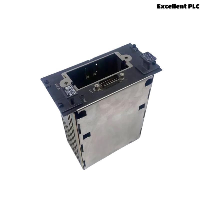
The Yokogawa AIP503 V-Net Coupler Module is a communication interface module designed for Yokogawa CENTUM VP and CENTUM CS Distributed Control Systems (DCS). It provides the interface between the Field Control Unit (FCU) and the Yokogawa V-Net real-time control network, enabling deterministic, high-speed communication among controllers, operator stations, engineering stations, and system gateways. The AIP503 supports redundant V-Net communication, ensuring high availability, fault tolerance, and reliable process control in mission-critical industrial applications.
Contents
- 1. Product Overview
- 2. Main Features
- 3. Typical Applications
- 4. Installation Preparation
- 5. Hardware Inspection
- 6. Module Installation
- 7. V-Net Cable Connection
- 8. Network Configuration
- 9. Commissioning Procedure
- 10. Functional Verification
- 11. Redundancy Test
- 12. Preventive Maintenance
- 13. Practical Installation Case
- 14. Frequently Asked Questions
Product Overview
The AIP503 provides the communication interface between the FCU and the Yokogawa V-Net control network. It enables deterministic real-time process communication, controller synchronization, alarm transmission, engineering access, and network redundancy for large-scale automation systems.
Main Features
- High-speed V-Net communication interface
- Support for redundant communication networks
- Real-time deterministic data transmission
- Industrial-grade reliability
- Fast controller synchronization
- Integrated status LED diagnostics
- Modular hot-replacement during maintenance windows
- Designed for continuous industrial operation
Typical Applications
- CENTUM VP Field Control Units
- CENTUM CS controllers
- Oil and gas production facilities
- Petrochemical plants
- Power generation systems
- Large-scale industrial process automation
Installation Preparation
- Review network architecture documentation.
- Verify module compatibility.
- Prepare ESD protection equipment.
- Confirm V-Net cable routing.
- Schedule an approved maintenance window.
Hardware Inspection
- Verify module model and revision.
- Inspect housing for damage.
- Check backplane connectors.
- Inspect V-Net cable connectors.
- Verify status indicators are undamaged.
Module Installation
- Place the controller in a safe maintenance condition.
- Wear an anti-static wrist strap.
- Insert the AIP503 fully into the designated slot.
- Secure the retaining screws.
- Verify complete backplane engagement.
- Connect all required communication cables.
V-Net Cable Connection
- Connect primary V-Net cable.
- Connect redundant V-Net cable if installed.
- Lock all cable connectors securely.
- Maintain recommended cable bending radius.
- Separate communication cables from power wiring.
Network Configuration
- Assign the correct controller node address.
- Configure communication domain parameters.
- Enable redundant communication channels.
- Verify controller registration.
- Synchronize engineering database settings.
Commissioning Procedure
VERIFY INSTALLATION
CONNECT V-NET CABLES
POWER ON CONTROLLER
VERIFY MODULE DETECTION
CHECK NETWORK STATUS
VERIFY REDUNDANT LINKS
TEST COMMUNICATION
BEGIN NORMAL OPERATION
Functional Verification
- Verify controller appears on V-Net.
- Confirm operator station communication.
- Verify engineering station connectivity.
- Test process data updates.
- Review diagnostic information.
Redundancy Test
- Disconnect the primary communication path.
- Verify automatic switchover.
- Confirm uninterrupted controller communication.
- Reconnect the primary network.
- Verify automatic recovery.
Preventive Maintenance
- Inspect connectors periodically.
- Verify cable integrity.
- Clean communication interfaces.
- Review network diagnostics.
- Perform redundancy testing during scheduled shutdowns.
Practical Installation Case
During the expansion of a refinery automation system, an AIP503 V-Net Coupler Module was installed in a new Field Control Unit to integrate the controller into the plant V-Net.
Following installation, the controller remained offline because the redundant communication cable had not been connected.
After completing the redundant cable installation:
- The controller appeared immediately on the V-Net.
- Engineering stations established communication.
- Operator stations displayed real-time process values.
- Redundant communication operated normally.
Frequently Asked Questions
What is the primary function of the AIP503?
The AIP503 provides the communication interface between Yokogawa Field Control Units and the V-Net real-time control network, enabling deterministic and redundant industrial communication.
Does the AIP503 support network redundancy?
Yes. The module supports redundant V-Net communication paths to improve system availability and maintain continuous process operation.
What should be verified after installation?
Verify controller detection, V-Net communication, redundant path operation, engineering station access, operator station connectivity, and the absence of communication alarms.
Summary
Proper installation of the Yokogawa AIP503 V-Net Coupler Module requires secure hardware mounting, correct V-Net cable connections, accurate network configuration, comprehensive communication testing, and redundancy verification. Following these procedures ensures reliable real-time communication, high system availability, and dependable industrial automation performance.