 Excellent PLC


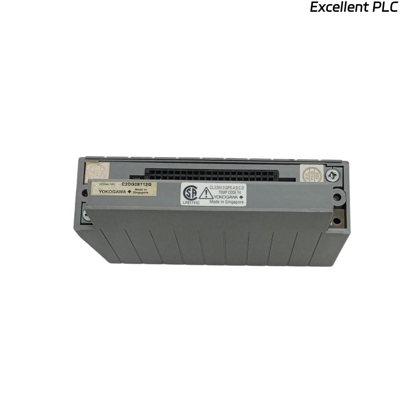
The Yokogawa ATA4S Pressure Clamp Terminal Block is a passive field wiring termination assembly used with Yokogawa CENTUM VP and CENTUM CS 3000 Distributed Control Systems (DCS). It provides secure pressure-clamp connections between field instruments and standard analog I/O modules. Although the ATA4S contains no electronic circuitry, incorrect wiring, damaged terminals, poor connector engagement, or environmental factors can lead to signal interruptions, unstable measurements, communication alarms, and field device failures. Proper troubleshooting focuses on verifying wiring integrity and mechanical connections.
Contents
- 1. Understanding Terminal Block Faults
- 2. Common Failure Symptoms
- 3. Typical Causes
- 4. Initial Inspection
- 5. Field Wiring Verification
- 6. Connector Inspection
- 7. Diagnostic Analysis
- 8. Recommended Troubleshooting Workflow
- 9. Corrective Actions
- 10. Functional Recovery Verification
- 11. Preventive Maintenance
- 12. Industrial Maintenance Case
- 13. Frequently Asked Questions
Understanding Terminal Block Faults
The ATA4S functions as the interface between field devices and Yokogawa analog I/O modules. Since it is a passive component, most failures are related to wiring quality, pressure-clamp contact condition, connector installation, or cable integrity. Improper installation may result in intermittent analog signals, increased electrical noise, inaccurate process measurements, or complete signal loss.
Common Failure Symptoms
- Analog signal is missing.
- Process value fluctuates unexpectedly.
- DCS reports input or output channel alarms.
- Signal is intermittent during equipment vibration.
- High electrical noise on analog channels.
- Incorrect process measurements.
- Several channels stop working simultaneously.
- Communication appears normal but field values are incorrect.
Typical Causes
- Incomplete wire insertion.
- Loose pressure-clamp connection.
- Damaged terminal contacts.
- Broken field cable.
- Incorrect terminal assignment.
- Poor cable shielding.
- Improper grounding.
- Connector not fully seated.
- Mechanical damage to the terminal block.
Initial Inspection
- Isolate cabinet power before inspection.
- Inspect the ATA4S housing.
- Verify pressure-clamp terminals.
- Inspect interface connectors.
- Check cable routing.
- Review DCS diagnostic information.
Field Wiring Verification
- Compare terminal numbers with wiring drawings.
- Confirm conductor insertion depth.
- Inspect wire insulation.
- Measure loop continuity.
- Verify cable shield grounding.
- Inspect conductor retention.
Connector Inspection
- Verify connector locking.
- Inspect connector pins.
- Check for contamination.
- Confirm full connector engagement.
- Inspect interface cable condition.
- Replace damaged connectors if required.
Diagnostic Analysis
| Observed Condition | Possible Diagnosis |
|---|---|
| Single channel unavailable | Loose conductor or damaged pressure-clamp terminal |
| Multiple channels unavailable | Loose connector or interface cable failure |
| Signal fluctuates | Poor conductor retention or electrical interference |
| High analog noise | Improper cable shielding or grounding |
| Incorrect measurement | Wrong terminal assignment or wiring error |
Recommended Troubleshooting Workflow
CHECK DCS DIAGNOSTICS
INSPECT TERMINAL BLOCK
VERIFY CONNECTOR INSTALLATION
CHECK FIELD WIRING
MEASURE CONTINUITY
VERIFY SHIELD GROUNDING
TEST SIGNAL OPERATION
CONFIRM NORMAL OPERATION
Corrective Actions
- Reconnect improperly inserted conductors.
- Replace damaged pressure-clamp contacts.
- Repair broken field wiring.
- Correct terminal assignments.
- Replace damaged interface cables.
- Improve cable shielding.
- Restore proper grounding.
- Replace the ATA4S if mechanical damage is confirmed.
Functional Recovery Verification
- Verify wiring continuity.
- Confirm stable analog signals.
- Compare field measurements with DCS values.
- Review diagnostic messages.
- Verify all connected channels.
- Monitor system stability during operation.
Preventive Maintenance
- Inspect pressure-clamp terminals regularly.
- Verify conductor retention.
- Inspect cable insulation.
- Maintain clean cabinet conditions.
- Check connector engagement.
- Perform routine loop inspections.
Industrial Maintenance Case
During preventive maintenance at a power generation facility, operators noticed intermittent flow transmitter readings connected through an ATA4S terminal block. Inspection showed that one field conductor had not been fully inserted into the pressure-clamp terminal after previous maintenance.
After reinserting the conductor, verifying continuity, inspecting connector engagement, and confirming proper grounding:
- The analog signal became stable.
- Flow measurements matched field instruments.
- DCS alarms disappeared.
- Normal process operation resumed without replacing the terminal block.
Frequently Asked Questions
Can the ATA4S fail electronically?
No. The ATA4S is a passive terminal block without active electronic components. Most faults are caused by wiring errors, damaged terminals, poor connector installation, or mechanical wear.
Why does the signal fluctuate after maintenance?
The most common causes are incomplete conductor insertion, loose pressure-clamp contacts, incorrect wiring, damaged cables, or inadequate shielding and grounding.
When should the ATA4S be replaced?
The ATA4S should be replaced if the pressure-clamp mechanism is damaged, the housing is cracked, terminal insulation has deteriorated, or reliable electrical contact cannot be maintained.
Summary
Effective troubleshooting of the Yokogawa ATA4S Pressure Clamp Terminal Block involves systematic inspection of field wiring, pressure-clamp terminals, interface connectors, cable continuity, grounding, and shielding. Regular preventive maintenance and proper installation practices help ensure dependable analog signal transmission and long-term reliability of Yokogawa CENTUM Distributed Control Systems.