

Yokogawa SNT511-5F installation problems are usually caused by fiber attenuation, incorrect ESB bus topology, or improper connection between the Optical ESB Bus Repeater Slave Module and Safety Node Unit rather than module hardware failure. In ProSafe-RS and CENTUM VP projects, proper installation directly affects long-distance communication stability across safety and control networks.
Contents
- SNT511-5F Optical ESB Bus Repeater Slave Module Overview
- SNT511-5F Function in Safety Networks
- ESB Network Architecture Planning
- Fiber Transmission Distance Requirements
- Installation Preparation Checklist
- Environmental Requirements
- SNT511-5F Module Installation Guide
- Optical Fiber Wiring Procedure
- ESB Bus Cable Connection
- Grounding and Noise Protection
- SNT511-5F Setup Procedure
- System Configuration Verification
- Communication Diagnostics Before Startup
- Commissioning and Validation
- Fiber Attenuation Assessment
- Redundancy Verification
- Network Performance Monitoring
- Maintenance Recommendations
- Real Commissioning Case
- FAQ
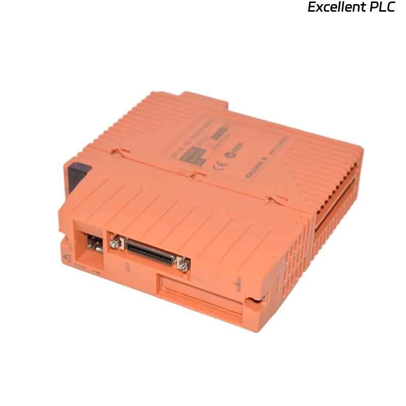
SNT511-5F Optical ESB Bus Repeater Slave Module Overview
The Yokogawa SNT511-5F is an Optical ESB Bus Repeater Slave Module designed to extend ESB Bus communication through fiber-optic transmission. The module operates together with the SNT411 Optical ESB Bus Repeater Master Module or N-ESB Bus modules to increase communication distance within safety and control systems. :contentReference[oaicite:0]{index=0}
SNT511-5F Function in Safety Networks
The module performs optical transport of ESB Bus communication used by safety control units, safety node units, and N-IO nodes. :contentReference[oaicite:1]{index=1}
- Extends communication distance
- Supports distributed safety systems
- Improves network flexibility
- Allows remote installation of safety nodes
ESB Network Architecture Planning
Before installation, engineers should verify:
- Master-slave relationship
- Network segmentation
- Fiber routing plans
- Redundant communication paths
- Safety node locations
Fiber Transmission Distance Requirements
The SNT511-5F supports optical ESB transmission distances ranging from 5 km to 50 km with a maximum of two connection stages. :contentReference[oaicite:2]{index=2}
Network planning should always account for attenuation budgets before installation.
Installation Preparation Checklist
- Fiber inspection completed
- OTDR testing completed
- Power supply verified
- ESB cable availability confirmed
- System drawings reviewed
- Node addressing validated
Environmental Requirements for SNT511-5F
The -5F suffix supports ISA G3 environments and operating temperatures from -20°C to 70°C. :contentReference[oaicite:3]{index=3}
- Stable cabinet temperature
- Low humidity exposure
- Controlled contamination levels
- Adequate airflow
SNT511-5F Module Installation Guide
- De-energize the cabinet.
- Inspect the backplane connector.
- Install the module into the designated slot.
- Verify locking mechanisms.
- Inspect communication ports.
- Record hardware information.
Optical Fiber Wiring Procedure
Fiber installation quality has a direct impact on network reliability.
- Verify transmit path
- Verify receive path
- Clean optical connectors
- Inspect fiber end faces
- Check attenuation values
In many startup projects, connector contamination causes communication failures despite normal module status indicators.
ESB Bus Cable Connection
The SNT511-5F connects to the ESB Bus Interface Module (SSB401) on the Safety Node Unit through an ESB Bus cable. :contentReference[oaicite:4]{index=4}
Grounding and Noise Protection
- Verify cabinet grounding
- Inspect shield continuity
- Check bonding points
- Eliminate grounding loops
SNT511-5F Setup Procedure
VERIFY POWER STATUS
CHECK MODULE LEDS
VERIFY FIBER LINK
CHECK NODE STATUS
VERIFY COMMUNICATION HEALTH
SAVE BASELINE VALUES
System Configuration Verification
System Configuration should verify:
- Node assignments
- Network routes
- Repeater definitions
- Safety network allocation
- Redundancy settings
Communication Diagnostics Before Startup
- Link status verification
- Node visibility testing
- Error counter review
- Latency measurement
- Fiber attenuation validation
SNT511-5F Commissioning and Validation
Commissioning should include:
- Normal communication verification
- Network load testing
- Node failover testing
- Alarm validation
- Power recovery testing
Fiber Attenuation Assessment
Yokogawa specifications indicate attenuation management is critical. When optical fiber attenuation is less than 3 dB, an attenuator may be required. Typical attenuation between repeater devices should be 3–4 dB. :contentReference[oaicite:5]{index=5}
Redundancy Verification
Safety applications require validation of communication behavior during:
- Fiber interruption
- Node failure
- Power interruption
- Communication recovery
Network Performance Monitoring
- Communication latency
- Error retries
- Link quality
- Fiber attenuation trend
- Node response time
Maintenance Recommendations
- Quarterly fiber inspection
- Annual attenuation testing
- Connector cleaning program
- Communication trend analysis
- Redundancy validation testing
Real SNT511-5F Commissioning Case
During startup of a chemical processing facility, multiple safety node communication alarms appeared after installation of a new optical ESB segment.
Measured values showed:
- Fiber attenuation: 8.7 dB
- Communication latency: 210 ms
- Error retries: increasing continuously
- Power supply status: normal
Initial diagnosis focused on replacing the SNT511-5F module.
However, OTDR testing identified a contaminated patch panel connection approximately 1.2 km from the control room.
After cleaning and re-terminating the fiber:
- Attenuation reduced to 2.8 dB
- Latency dropped below 18 ms
- Error counters stabilized
- Communication alarms disappeared
We observed that fiber infrastructure issues produced symptoms almost identical to module failure.
SNT511-5F Installation Guide FAQ
What is the main purpose of the SNT511-5F module?
The module extends ESB Bus communication through optical fiber networks in Yokogawa safety systems.
What transmission distance can be supported?
The optical ESB network can be extended from 5 km up to 50 km depending on architecture and attenuation conditions. :contentReference[oaicite:6]{index=6}
What is the most common installation problem?
Fiber attenuation and connector contamination are more common than hardware defects during commissioning.
Summary: A successful Yokogawa SNT511-5F Installation Guide focuses on fiber quality, attenuation control, ESB network architecture, System Configuration verification, and comprehensive communication commissioning.