

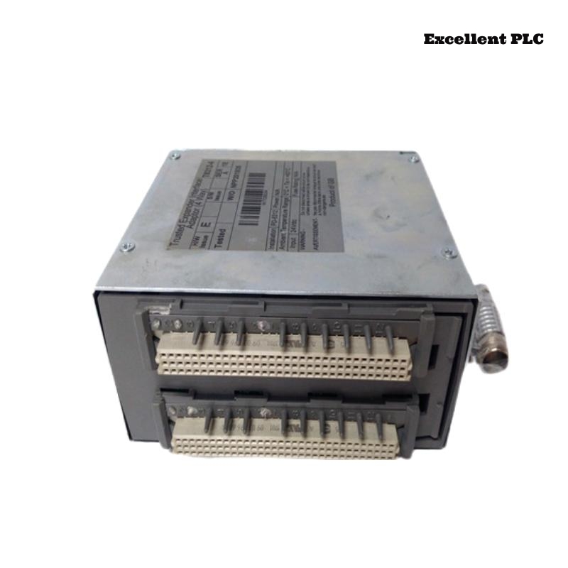
The ICS Triplex T8312 Expansion Interface Adapter is a key coupling component between the main controller chassis and one or more expansion chassis (such as T8300).
Although it is often treated as a simple interface card, field experience shows that a large number of intermittent system faults originate here.
This article focuses on real engineering practice: what fails, how to confirm it, how to install it correctly, and how to validate it through configuration and application logic.
Typical Fault Symptoms Related to T8312
When the T8312 is degraded or incorrectly installed, the system rarely reports a single clear error. Common symptoms include:
• Expansion rack not detected at startup
• Expansion rack detected but I/O modules intermittently offline
• Communication errors only after warm restart
• System enters RUN but trips shortly after
• Random I/O mismatch alarms without hardware changes
These symptoms are often misattributed to processors or I/O modules.
Common Hardware Failure Points
From refurbishment and replacement history, the most frequent issues are:
• Edge connector wear due to repeated insertions
• Oxidation on expansion bus signal contacts
• Micro-cracks in PCB traces near the connector area
• Mechanical stress caused by uneven chassis mounting
The T8312 is especially sensitive to mechanical alignment and connector condition.
How to Confirm the T8312 Is the Root Cause
Before replacing major system components, perform the following checks:
• Swap the T8312 with a known-good unit
• Observe whether the fault moves with the adapter
• Inspect connector pins under magnification
• Check that the adapter is fully seated and locked
• Verify no lateral force from attached expansion cables
If multiple expansion racks fail through the same adapter, suspicion should focus on the T8312.
Correct Installation Procedure (Field-Recommended)
Improper installation is one of the main reasons T8312 units develop long-term faults.
Recommended steps:
• Power down the entire Trusted® system
• Observe ESD protection requirements
• Ensure chassis mounting is rigid and grounded
• Insert the T8312 straight into the slot (no angle)
• Apply even pressure until fully seated
• Secure retaining screws to prevent vibration
Never insert or remove the T8312 with power applied.
Expansion Cable Connection Guidelines
The interface adapter is highly sensitive to cable handling.
Best practices:
• Use only approved expansion interface cables
• Avoid sharp bends near the connector
• Maintain consistent cable length within the same chain
• Do not overtighten cable strain reliefs
• Keep expansion cables away from high-noise power wiring
Poor cabling often manifests as temperature-dependent faults.
System Configuration Example (TSC Level)
The T8312 itself does not execute logic, but it must be correctly referenced in the system topology.
Typical configuration concept:
Important notes:
• The expansion interface must be enabled before the rack
• Multiple interfaces require explicit mapping
• Disabled or undefined adapters lead to silent communication failures
Expansion Rack Association Example
A mismatch between interface and rack definition is a common commissioning error.
Application-Level Diagnostic Logic Example
Many experienced engineers add explicit health checks for the expansion interface:
This prevents the system from running when expansion communication is degraded.
Runtime Supervision for Intermittent Faults
To catch vibration- or temperature-related issues:
This logic is especially useful for faults that only appear after hours or days of operation.
Commissioning Test Logic (Temporary)
During commissioning only:
Expected behavior:
• Expansion racks go offline cleanly
• System enters defined safe state
⚠️ Remove all forces before handover.
Repair vs Replacement Considerations
In safety-certified systems:
• Connector wear and PCB cracks are not recommended for onsite repair
• Cleaning may restore function temporarily but is not a long-term fix
• Replacement is usually the compliant and reliable option
The T8312 should be treated as a precision interface, not a passive accessory.
Post-Installation Verification Checklist
After installing or replacing a T8312:
• Expansion racks detected consistently
• No COMM_ERROR flags during extended runtime
• Stable behavior after multiple power cycles
• No forced states remain in configuration or logic
Only after these checks should the system be released.
Practical Engineering Conclusion
The T8312 does not fail loudly.
It fails politely, intermittently, and expensively if misunderstood.
Most “mysterious” expansion issues disappear once the interface adapter is installed correctly and monitored explicitly in logic.
Treat it as a communication authority point, not a simple connector.