

Table of Contents
- Bently Nevada 170133-090-00 Troubleshooting Entry
- Channel Fault Symptom Evaluation
- Diagnostic Sequence for Dual Proximitor Modules
- Root Cause Patterns in Dual-Channel Faults
- Real Case: Channel Offset in Operation
- Correction Strategy and Signal Recovery
- FAQ
- Technical Summary
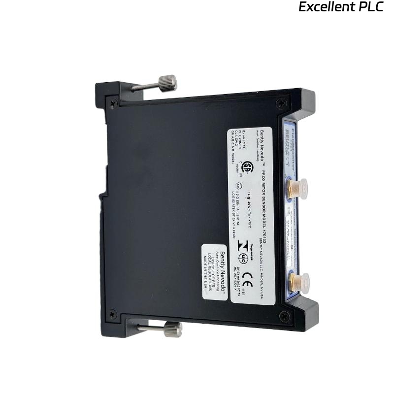
Bently Nevada 170133-090-00 Troubleshooting Entry
Bently Nevada 170133-090-00 dual proximitor module troubleshooting reveals that channel offset, signal drift, or inconsistent readings are mainly caused by probe gap deviation, calibration mismatch, or wiring issues rather than module failure.
This guide provides a structured fault diagnosis method based on dual-channel comparison.
Channel Fault Symptom Evaluation
- Persistent offset between Channel A and B
- Signal drift during temperature changes
- One channel stable, the other fluctuating
- Loss of signal in one channel
Symptom patterns guide troubleshooting direction.
Diagnostic Sequence for Dual Proximitor Modules
IF channel offset observed:
    measure gap voltage for both channels
    adjust probe positioning

IF signal drift:
    check thermal effects
    inspect mounting stability

IF one channel unstable:
    verify cable and connector
    inspect probe condition

IF no signal:
    check backplane interface
    verify module power supply
This sequence ensures systematic fault isolation.
Root Cause Patterns in Dual-Channel Faults
- Probe gap inconsistency between channels
- Calibration mismatch due to different system lengths
- Cable degradation or connector issues
- Improper module seating in rack
Real Case: Channel Offset in Operation
In a centrifugal compressor system, Channel A showed stable readings at 3.2 mm/s, while Channel B remained at 5.8 mm/s.
Analysis:
- Channel B gap voltage measured -6.8V
- Channel A gap voltage at -9.1V
Root Cause: Incorrect probe gap adjustment on Channel B.
Solution:
- Adjusted probe gap to achieve -9V
- Rechecked calibration alignment
Result: Both channels stabilized at approximately 3.5 mm/s.
Correction Strategy and Signal Recovery
- Align probe gap voltages between channels
- Verify consistent system configuration
- Inspect wiring and connectors
- Ensure proper module installation
Accurate correction ensures reliable monitoring.
FAQ
Why is there a constant offset between channels?
This is typically caused by probe gap differences or calibration mismatch.
How to correct signal drift?
Check thermal effects, mounting stability, and calibration settings.
Is module replacement required?
No, most faults are related to installation and configuration.
Technical Summary
This Troubleshooting Guide shows that Bently Nevada 170133-090-00 module issues are mainly due to probe setup and system configuration inconsistencies. A structured fault diagnosis approach ensures stable and accurate dual-channel vibration monitoring.