

Table of Contents
- Bently Nevada 170180-02-00 Installation Guide Entry
- Role of External Transducer I/O Module in Velocity Monitoring
- Engineering Design Logic for 2-Wire Velocity Sensors
- Wiring and Loop-Powered Signal Integration
- System Configuration and Signal Scaling
- Commissioning Under Dynamic Conditions
- FAQ
- Technical Summary
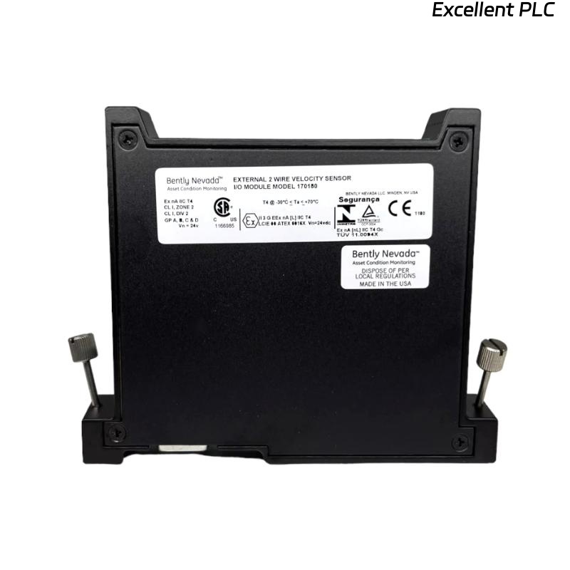
Bently Nevada 170180-02-00 Installation Guide Entry
Bently Nevada 170180-02-00 external transducer I/O module installation issues are most commonly caused by incorrect 2-wire velocity sensor wiring or loop power misconfiguration, leading to signal loss or distorted vibration readings rather than module failure.
This Installation Guide focuses on correct loop-powered sensor integration and stable FieldMonitor system configuration.
Role of External Transducer I/O Module in Velocity Monitoring
- Interfaces 2-wire velocity transducers with monitoring systems
- Provides dual-channel input for vibration signals
- Supports 4–20 mA loop-powered signal transmission
The module enables reliable vibration velocity measurement in rotating machinery. :contentReference[oaicite:0]{index=0}
Engineering Design Logic for 2-Wire Velocity Sensors
- Each channel supports one loop-powered velocity sensor
- Power and signal share the same wiring pair
- Requires stable 24V DC supply for loop operation
Engineering Insight: Incorrect loop resistance or polarity will prevent current loop stabilization, resulting in zero or drifting signals.
Wiring and Loop-Powered Signal Integration
- Connect 24V DC loop supply through the I/O module
- Wire sensor in series with current loop (4–20 mA)
- Verify polarity (positive loop direction)
- Use shielded cables to minimize EMI
IF no signal:
    check loop continuity
    verify 24V supply

IF signal fixed at 4 mA:
    check sensor output
    verify loop resistance

IF signal unstable:
    inspect grounding
    check EMI interference
Real Case:
In a cooling tower fan system, vibration signal remained constant at 4 mA. Loop voltage measured only 12V due to excessive cable resistance (~600Ω). After reducing cable length and improving wiring, loop voltage increased to 24V and signal stabilized between 6–12 mA depending on vibration level.
System Configuration and Signal Scaling
- Configure input type as velocity (mm/s)
- Set scaling based on 4–20 mA range
- Verify frequency response (typically 2 Hz to 10 kHz)
The module supports accurate vibration velocity measurement across industrial ranges. :contentReference[oaicite:1]{index=1}
Commissioning Under Dynamic Conditions
- Monitor signal during startup and steady-state operation
- Compare readings with portable vibration analyzer
- Validate both channels independently
Commissioning ensures reliable real-time monitoring.
FAQ
Why is the signal stuck at 4 mA?
This usually indicates no vibration signal or loop wiring issue.
Can proximity probes be used with this module?
No, this version is optimized for 2-wire velocity sensors.
What is the required power supply?
Typically 24V DC for loop-powered operation.
Technical Summary
This Installation Guide shows that Bently Nevada 170180-02-00 module performance depends on correct loop wiring, proper power supply, and accurate signal scaling. Proper setup ensures stable and accurate vibration velocity monitoring.