

Table of Contents
- Bently Nevada 177230-02 Troubleshooting Entry
- High-Range Signal Symptoms and Interpretation
- Fault Diagnosis Logic Based on Signal Behavior
- Root Causes in High-Vibration Monitoring Systems
- Real Case: Signal Compression Due to Installation Error
- Recovery Strategy and Optimization
- FAQ
- Technical Summary
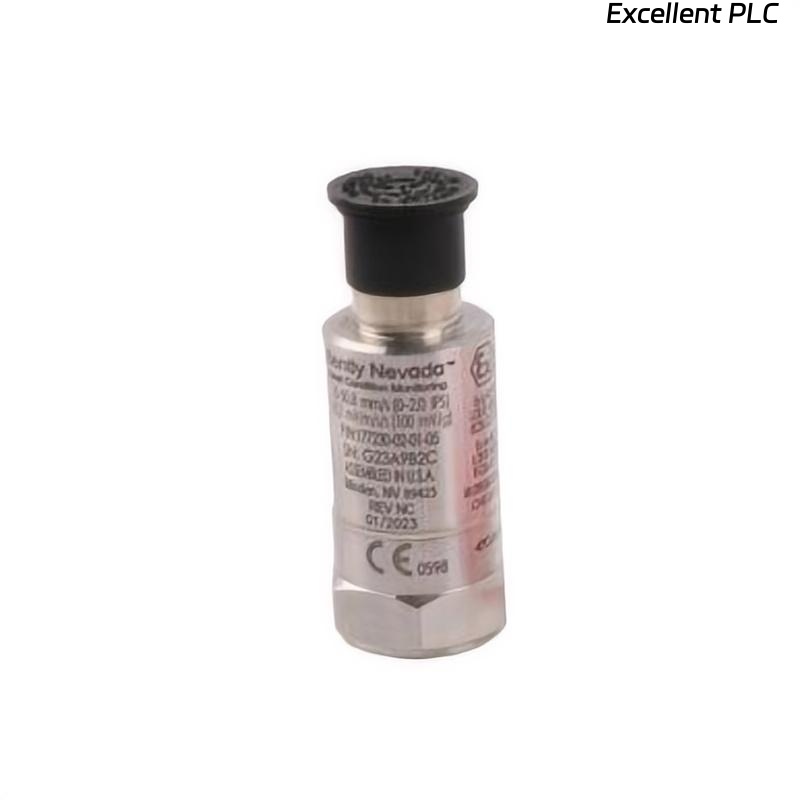
Bently Nevada 177230-02 Troubleshooting Entry
Bently Nevada 177230-02 seismic sensor troubleshooting indicates that abnormal signal behavior—such as early saturation, compressed output, or instability—is usually caused by configuration mismatch or installation defects rather than sensor hardware failure.
This guide focuses on interpreting high-range 4–20 mA signal behavior for accurate fault diagnosis.
High-Range Signal Symptoms and Interpretation
- Signal saturates too early → scaling mismatch
- Signal range compressed → poor vibration transmission
- Fluctuating signal → EMI or grounding issue
- Intermittent drop → wiring or connector fault
Understanding signal behavior is key to efficient troubleshooting.
Fault Diagnosis Logic Based on Signal Behavior
IF signal saturates early:
    verify PLC scaling
    confirm sensor range

IF signal compressed:
    check mounting location
    verify vibration transmission

IF signal unstable:
    inspect grounding
    check EMI sources

IF intermittent:
    inspect connectors and cables
This logic aligns with real field diagnostics used in vibration monitoring systems.
Root Causes in High-Vibration Monitoring Systems
- Mismatch between sensor range and system configuration
- Poor mechanical coupling reducing signal amplitude
- Electrical interference affecting loop stability
- Incorrect installation location
Real Case: Signal Compression Due to Installation Error
In a large industrial blower, vibration readings remained between 5–10 mA despite high noise levels.
Observed Data:
- Signal did not scale with load increase
Analysis: Mechanical issue suspected.
Root Cause: Sensor installed on non-structural support bracket.
Solution:
- Relocated sensor to bearing housing
Result: Signal increased to 8–17 mA, matching actual vibration (~30 mm/s).
Recovery Strategy and Optimization
- Align PLC scaling with sensor range
- Ensure rigid mounting and proper surface preparation
- Use shielded cables and proper grounding
- Perform periodic validation with reference instruments
Preventive diagnostics significantly improve system reliability.
FAQ
Why does the signal saturate early?
This is usually caused by incorrect PLC scaling.
How to confirm installation issues?
Compare sensor output with a portable vibration analyzer.
Is sensor failure common?
No, most issues are related to installation or configuration.
Technical Summary
This Troubleshooting Guide demonstrates that Bently Nevada 177230-02 faults are mainly caused by scaling mismatch, installation issues, and signal integrity problems. A structured diagnostic approach ensures accurate high-range vibration monitoring.