

Table of Contents
- 200200-03-03-05 Fault Diagnosis Entry
- Common Symptoms of 200200-03-03-05 Module Fault
- Fault Diagnosis Process
- Common Causes of Dual Input Module Fault
- Diagnostic Methods and Tools
- Corrective Actions and Recovery
- Real Troubleshooting Case
- Troubleshooting FAQ
- Final Technical Summary
200200-03-03-05 Fault Diagnosis Entry
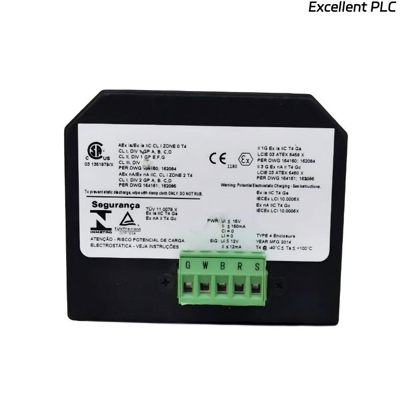
The Bently Nevada 200200-03-03-05 Trendmaster proTim-R dual input module can experience issues such as signal loss, noise, or inconsistencies between the two input channels. These problems are often caused by wiring issues, incorrect calibration, or electromagnetic interference (EMI).
Common Symptoms of 200200-03-03-05 Module Fault
- Intermittent or complete signal loss from one or both input channels
- Erratic signal output or noise spikes during machine operation
- Discrepancies between readings of the two input channels
- Frequent system alarms despite normal machine operation
Fault Diagnosis Process
To diagnose faults with the 200200-03-03-05 module, perform the following steps:
- Check all wiring connections and verify that they are secure and free from damage
- Inspect the grounding and shielding to eliminate EMI as a cause of interference
- Use a multimeter to check continuity and ensure the wiring is intact
- Validate the configuration settings in the system software to ensure proper sensor input ranges and thresholds
  // Fault Diagnosis Logic
  IF Signal_Loss_OR_Signal_Variability THEN
      Inspect_Connector_Integrity();
      Verify_Shielding_And_Grounding();
  ELSE
      Recheck_Configuration_Settings();
  END_IF;
Common Causes of Dual Input Module Fault
- Loose or damaged wiring connections between the module and sensors
- Electromagnetic interference (EMI) affecting the sensor signal integrity
- Incorrect grounding or improper shielding of cables and inputs
- Incorrect sensor calibration or incompatible sensor settings
- Physical damage to the module or connectors
Diagnostic Methods and Tools
- Multimeter to verify cable continuity and proper connections
- Oscilloscope to check for signal noise and voltage fluctuations
- Vibration analyzer to cross-check sensor output with actual machine vibration
Corrective Actions and Recovery
- Replace damaged wiring or connectors
- Reroute cables to minimize interference from nearby electrical sources
- Ensure proper grounding and shielding of cables and inputs
- Recalibrate sensors and check configuration settings in the system software
Real Troubleshooting Case
In a commissioning scenario, the 200200-03-03-05 module exhibited unstable readings during high-speed operations of a pump:
- The signal from one input channel fluctuated significantly during load changes
- Upon investigation, it was found that the sensor wiring was too close to power cables, leading to EMI interference
After rerouting the sensor cables and ensuring proper grounding, both channels stabilized, and the system provided reliable readings:
- Signal consistency was restored during all operating conditions
- The system’s alarm thresholds were adjusted based on stable input signals
Troubleshooting FAQ
What should I do if one of the input channels is not receiving a signal?
Check the wiring and connections for continuity, and ensure that the sensor is correctly connected. Also, verify that there is no physical damage to the cable or connectors.
How can I reduce EMI interference during installation?
To reduce EMI, ensure that cables are shielded and routed away from sources of electromagnetic interference. Proper grounding of the module and cables is essential for signal integrity.
What calibration settings should I use for the sensors?
Calibration settings should match the operational parameters of the machine and sensor specifications. Verify the sensor ranges in the system configuration to ensure accurate readings.
Final Technical Summary
The Bently Nevada 200200-03-03-05 Troubleshooting Guide emphasizes that ensuring secure wiring, proper grounding, and correct system configuration are critical to maintaining reliable operation of the Trendmaster proTim-R dual input module. By following these troubleshooting steps, you can resolve most common issues and maintain optimal system performance.