

Table of Contents
- Bently Nevada 200355-01-00-00 Fault Diagnosis Entry
- Accelerometer Fault Symptoms
- Field Fault Diagnosis Process
- Common Causes of Signal Integrity Fault
- Diagnostic Methods and Tools
- Corrective Actions and System Recovery
- Real Troubleshooting Case
- Troubleshooting FAQ
- Final Technical Summary
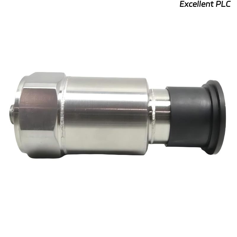
Bently Nevada 200355-01-00-00 Fault Diagnosis Entry
Bently Nevada 200355-01-00-00 accelerometer Troubleshooting typically reveals that most faults originate from installation and signal path issues rather than sensor failure. Misinterpretation of vibration data is common in field environments.
Accelerometer Fault Symptoms
- Frequent false alarms without mechanical issues
- Unstable or noisy signal waveform
- Inconsistent readings between sensors
- Sudden spikes during machine operation
Field Fault Diagnosis Process
Experienced engineers follow a structured troubleshooting approach:
- Check signal quality (bias voltage and waveform)
- Inspect mechanical mounting condition
- Evaluate cable routing and shielding
  // Troubleshooting Logic
  IF Signal_Unstable THEN
      Check_Shielding_And_Ground();
  ELSE IF Reading_High THEN
      Inspect_Mounting_Location();
  ELSE
      Verify_System_Config();
  END_IF;
Common Causes of Signal Integrity Fault
- Improper mounting location or loose installation
- Ground loop or poor shielding
- Damaged or contaminated connectors
- Electromagnetic interference
- Incorrect system configuration
Diagnostic Methods and Tools
- Measure bias voltage (~10 VDC)
- Use oscilloscope for waveform analysis
- Perform tap test for sensor validation
- Compare readings with portable vibration analyzer
Corrective Actions and System Recovery
- Reinstall sensor correctly
- Improve grounding and shielding
- Replace damaged cables or connectors
- Reconfigure system parameters
Real Troubleshooting Case
In a water pump system, repeated alarms were reported:
- Measured vibration: 9.7 mm/s
- No mechanical fault detected
Investigation showed:
- Shield grounded at both ends
- Sensor slightly loose
After correction:
- Implemented single-point grounding
- Re-tightened mounting
Result:
- Reading normalized to 3.3 mm/s
- System stable
Troubleshooting FAQ
Why do false alarms occur?
Usually due to installation or signal interference issues.
How can I confirm sensor health?
Use tap test and compare waveform response.
Is grounding really important?
Yes. Improper grounding is a major cause of signal instability.
Final Technical Summary
The Bently Nevada 200355-01-00-00 Troubleshooting Guide highlights that structured diagnosis focusing on installation and signal path resolves most issues. Proper setup ensures reliable monitoring and avoids unnecessary sensor replacement.