

Table of Contents
- 21508-02-12-05-02 Fault Diagnosis Entry
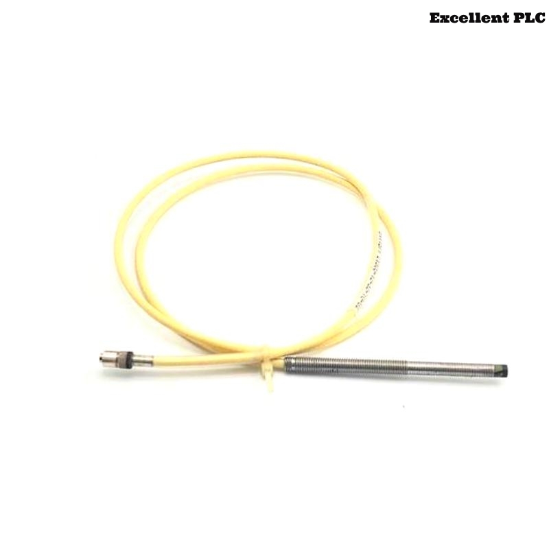
- 7200 8 mm Reverse Mount Probe Fault Symptoms
- Reverse Mount Troubleshooting Logic
- Common Causes of Reverse Probe Signal Faults
- Diagnostic Workflow and Measurement Analysis
- Corrective Actions and Signal Recovery
- Real Reverse Mount Troubleshooting Case
- Troubleshooting FAQ
- Final Technical Summary
21508-02-12-05-02 Fault Diagnosis Entry
Bently Nevada 21508-02-12-05-02 Troubleshooting often reveals that reverse mount probe systems are highly sensitive to bracket resonance, alignment deviation, and thermal movement. In many machinery protection systems, unstable readings originate from mechanical installation conditions rather than probe electronics failure.
7200 8 mm Reverse Mount Probe Fault Symptoms
- Gap voltage instability during operation
- Intermittent displacement alarms
- Waveform distortion during thermal expansion
- Signal spikes near operating speed
Reverse Mount Troubleshooting Logic
Experienced engineers usually diagnose reverse-mounted probes by evaluating mechanical conditions before replacing hardware:
- Inspect bracket rigidity and resonance behavior
- Verify probe alignment relative to the shaft
- Check armored cable support and grounding continuity
- Then evaluate monitoring electronics and proximitor outputs
  // Reverse Probe Fault Logic
  IF Waveform_Distortion = TRUE THEN
      Check_Bracket_Resonance();
      Verify_Probe_Angle();
  ELSE IF Gap_Voltage_Drift = TRUE THEN
      Inspect_Thermal_Expansion();
      Verify_Cable_Support();
  ELSE
      Test_Proximitor_System();
  END_IF;
Common Causes of Reverse Probe Signal Faults
- Bracket resonance during operation
- Incorrect reverse probe alignment
- Armored cable vibration transfer
- Grounding and shielding problems
- Thermal expansion affecting mounting geometry
Diagnostic Workflow and Measurement Analysis
- Measure static and dynamic gap voltage
- Observe waveform behavior during startup
- Inspect mounting bracket vibration under load
- Compare displacement readings across monitoring channels
Corrective Actions and Signal Recovery
- Reinforce reverse mounting brackets
- Adjust probe alignment and target angle
- Install vibration-resistant cable supports
- Improve shielding and grounding continuity
Real Reverse Mount Troubleshooting Case
In a gas turbine monitoring system, repeated displacement alarms occurred during thermal load increase:
- Gap voltage fluctuated between -9V and -5.9V
- Signal spikes exceeded baseline by 39%
Investigation revealed:
- Reverse mounting bracket resonance amplified shaft vibration frequencies
After corrective actions:
- Reinforced bracket structure
- Adjusted probe position and cable support routing
Result:
- Stable vibration monitoring restored
- False alarms eliminated during operation
Troubleshooting FAQ
Why are reverse mount probes sensitive to resonance?
Reverse mounting structures can amplify vibration frequencies if bracket rigidity is insufficient.
Can thermal expansion affect reverse probe alignment?
Yes. Temperature changes may shift mounting geometry and alter gap voltage stability.
Should the probe be replaced after unstable displacement alarms?
No. Mechanical mounting and alignment conditions should be inspected before replacing hardware.
Final Technical Summary
The Bently Nevada 21508-02-12-05-02 Troubleshooting Guide highlights that successful Fault Diagnosis in reverse mount applications depends on understanding structural resonance, thermal movement, armored cable dynamics, and precise probe alignment.