

Table of Contents
- VI702 Fault Diagnosis Entry
- Interface Card Fault Symptoms
- Engineering Troubleshooting Analysis
- Common Causes of Communication Faults
- Diagnostic Workflow and Signal Verification
- Corrective Actions and System Recovery
- Real Industrial Troubleshooting Experience
- Troubleshooting FAQ
- Final Technical Summary
VI702 Fault Diagnosis Entry
YOKOGAWA VI702 Troubleshooting commonly identifies unstable grounding continuity, improper module seating, and communication cable EMI exposure as major causes of industrial communication instability. In many automation systems, installation issues create symptoms that resemble hardware module failures.
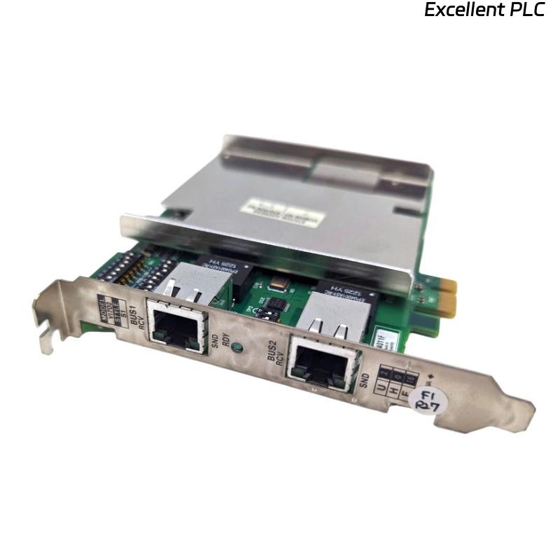
Interface Card Fault Symptoms
- Intermittent communication loss
- I/O signal update delays
- Communication alarm activation
- Controller data synchronization faults
- Unexpected module initialization failures
Engineering Troubleshooting Analysis
Experienced field engineers usually isolate communication faults by evaluating wiring quality and grounding continuity before replacing interface modules.
- Verify power supply stability
- Inspect communication cable shielding continuity
- Check module seating and backplane connections
- Then evaluate interface card hardware diagnostics
  // Interface Card Diagnostic Logic
  IF Communication_Fault = TRUE THEN
      Verify_Cable_Integrity();
      Inspect_Backplane_Connection();
  ELSE IF Signal_Noise_Level > Threshold THEN
      Check_Grounding();
      Inspect_Cable_Routing();
  ELSE
      Test_Interface_Module();
  END_IF;
Common Causes of Communication Faults
- Improper module installation
- Ground loop interference
- Communication cable EMI exposure
- Loose backplane connections
- Incorrect communication parameter configuration
Diagnostic Workflow and Signal Verification
- Measure communication signal stability
- Inspect cabinet grounding continuity
- Verify module diagnostic indicators
- Compare communication performance across adjacent modules
Corrective Actions and System Recovery
- Re-seat interface modules securely
- Repair grounding continuity problems
- Re-route communication cables away from inverter systems
- Verify communication parameter consistency
Real Industrial Troubleshooting Experience
In a petrochemical distributed control system, repeated communication alarms appeared after startup:
- I/O update timing became unstable
- Controller synchronization alarms appeared intermittently
Investigation revealed:
- Communication wiring installed adjacent to VFD power systems
- Loose interface module seating within the rack assembly
After corrective actions:
- Improved cable routing and shielding continuity
- Re-secured module installation within the rack
Result:
- Stable industrial communication restored
- System synchronization reliability improved
Troubleshooting FAQ
Why do communication alarms appear intermittently?
EMI interference, unstable grounding continuity, and loose module connections are common causes.
Can inverter systems affect interface card communication?
Yes. High-power inverter systems may introduce electrical noise into communication networks.
Should interface cards be replaced immediately after communication instability appears?
No. Wiring integrity, grounding continuity, and module installation quality should be inspected first.
Final Technical Summary
The YOKOGAWA VI702 Troubleshooting Guide highlights that successful Fault Diagnosis depends on stable communication wiring, reliable grounding continuity, proper interface module Setup, and disciplined industrial automation analysis.