

Table of Contents
- F3XH04-3N Fault Diagnosis Entry
- High-Speed Signal Fault Symptoms
- Engineering Troubleshooting Analysis
- Common Causes of Pulse Signal Faults
- Diagnostic Workflow
- Corrective Actions and Recovery
- Industrial Troubleshooting Example
- Troubleshooting FAQ
- Technical Summary
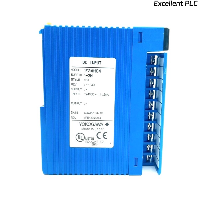
F3XH04-3N Fault Diagnosis Entry
YOKOGAWA F3XH04-3N troubleshooting commonly identifies grounding continuity defects, EMI interference, unstable 24V DC power supplies, encoder signal instability, and improper pulse configuration as major causes of high-speed signal acquisition faults and PLC synchronization instability.
High-Speed Signal Fault Symptoms
- Intermittent pulse signal loss
- Encoder count instability
- Missed interrupt signals
- False triggering of high-speed inputs
- PLC synchronization and positioning errors
Engineering Troubleshooting Analysis
Industrial automation engineers generally isolate F3XH04-3N faults by evaluating grounding continuity, encoder signal integrity, PLC power stability, and pulse input configuration before replacing hardware components.
  // High-Speed Input Diagnostic Logic
  IF Pulse_Loss = TRUE THEN
      Verify_Encoder_Signal();
      Inspect_Signal_Cabling();
  ELSE IF False_Trigger = TRUE THEN
      Verify_Grounding_System();
      Inspect_Shielding_Integrity();
  ELSE
      Test_F3XH04_3N_Module();
  END_IF;
Common Causes of Pulse Signal Faults
- Improper shield grounding
- Signal wiring routed beside inverter cables
- Loose signal terminals
- Incorrect pulse-catch configuration
- Unstable 24V DC power supplies
Diagnostic Workflow
- Inspect module LED diagnostic indicators
- Verify encoder and sensor signal integrity
- Measure 24V DC power stability
- Inspect shielded signal cable termination
- Verify PLC interrupt and pulse-catch settings
Corrective Actions and Recovery
- Repair grounding continuity defects
- Separate signal and inverter cable routing
- Secure signal connectors and terminals
- Correct pulse-catch and interrupt configuration
Industrial Troubleshooting Example
In an industrial conveyor synchronization system, encoder pulse instability appeared intermittently during high-speed operation:
- Position tracking errors increased
- Pulse acquisition became unstable during motor acceleration
Investigation revealed:
- Encoder signal cables installed beside VFD motor power wiring
- Weak PLC cabinet grounding continuity
After corrective actions:
- Separated encoder and inverter cable routing
- Improved cabinet grounding continuity
Result:
- Stable high-speed pulse acquisition restored
- PLC synchronization reliability improved significantly
Troubleshooting FAQ
Can EMI interference affect high-speed pulse acquisition?
Yes. Improper cable routing near inverter or motor wiring can create pulse distortion and false triggering conditions.
Should the F3XH04-3N be replaced immediately after pulse instability appears?
No. Grounding continuity, encoder signal integrity, PLC configuration, and power stability should be verified first.
Why is pulse-catch configuration important?
Proper pulse-catch configuration allows the module to detect short-duration pulse signals reliably during high-speed operation.
Technical Summary
The YOKOGAWA F3XH04-3N Troubleshooting Guide highlights that successful high-speed PLC signal diagnosis depends on stable power distribution, reliable grounding continuity, optimized signal wiring practices, and disciplined industrial automation analysis procedures.