

Table of Contents
- VI702-S1 Fault Diagnosis Entry
- Communication Fault Symptoms
- Engineering Troubleshooting Analysis
- Common Causes of Communication Faults
- Diagnostic Workflow
- Corrective Actions and Recovery
- Industrial Troubleshooting Example
- Troubleshooting FAQ
- Technical Summary
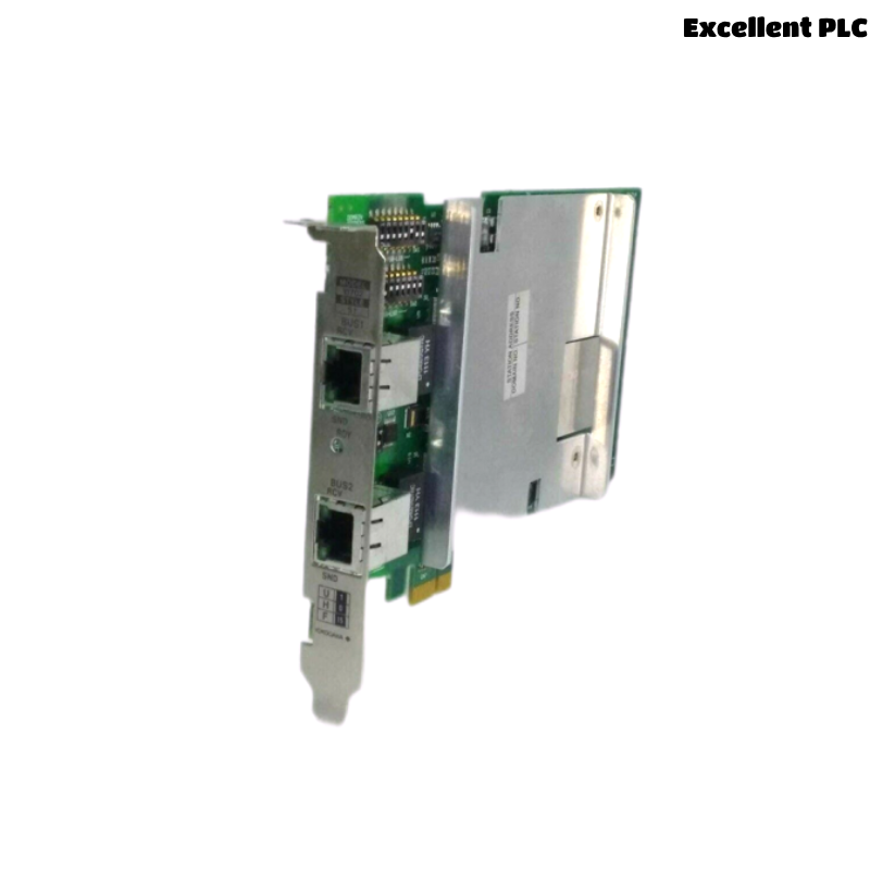
VI702-S1 Fault Diagnosis Entry
YOKOGAWA VI702-S1 troubleshooting commonly identifies communication connector issues, network topology faults, grounding continuity defects, EMI interference, and communication cable problems as major causes of Vnet/IP communication instability and DCS synchronization alarms.
Communication Fault Symptoms
- Vnet/IP communication alarms
- Network synchronization instability
- Controller communication interruptions
- Communication timeout alarms
- Process data transmission delays
Engineering Troubleshooting Analysis
Industrial automation engineers generally isolate VI702-S1 communication faults by evaluating interface status, communication cable integrity, grounding continuity, and network topology conditions before replacing hardware.
  // Communication Diagnostic Logic
  IF Communication_Alarm = TRUE THEN
      Verify_VI702_S1_Interface();
      Inspect_Network_Cable_Status();
  ELSE IF Synchronization_Unstable = TRUE THEN
      Verify_Grounding_System();
      Inspect_EMI_Exposure();
  ELSE
      Test_VI702_S1_Communication_Module();
  END_IF;
Common Causes of Communication Faults
- Loose communication connectors
- Damaged network communication cables
- Grounding continuity defects
- Improper Vnet/IP topology configuration
- Communication wiring routed near power cables
Diagnostic Workflow
- Inspect module communication interfaces
- Verify network cable continuity
- Measure cabinet grounding continuity
- Inspect EMI exposure conditions
- Verify network topology and redundancy status
Corrective Actions and Recovery
- Re-secure communication connectors
- Replace damaged communication cables
- Repair grounding continuity defects
- Correct network topology configuration
Industrial Troubleshooting Example
In a petrochemical CENTUM VP system, intermittent controller communication instability appeared during plant startup:
- Operator stations reported synchronization alarms
- Communication delays increased during motor loading conditions
Investigation revealed:
- Loose VI702-S1 communication interface connection
- Communication cables installed beside VFD power wiring
After corrective actions:
- Re-secured communication interfaces
- Separated communication and power cable routing
Result:
- Stable Vnet/IP communication restored
- DCS network reliability improved significantly
Troubleshooting FAQ
Can loose communication interfaces cause Vnet/IP alarms?
Yes. Loose communication interfaces can create intermittent communication interruptions and unstable network synchronization.
Should the VI702-S1 be replaced immediately after communication alarms appear?
No. Communication cables, grounding continuity, connector integrity, and network configuration should be verified first.
Why is communication cable routing important?
Proper routing minimizes EMI exposure and improves long-term industrial communication reliability.
Technical Summary
The YOKOGAWA VI702-S1 Troubleshooting Guide highlights that successful communication fault diagnosis depends on secure interface connections, stable grounding continuity, optimized communication cable routing, and disciplined industrial network maintenance procedures.