

The Yokogawa ADV561 Digital Output Module is a high-density 64-channel digital output module designed for CENTUM VP and other Yokogawa FIO systems. It provides reliable 24 VDC current-sink transistor outputs for controlling relays, solenoid valves, contactors, indicator lamps, and other field equipment. Proper installation, wiring, and commissioning are essential for achieving stable system operation and minimizing future maintenance requirements.
Contents
- 1. ADV561 Digital Output Module Overview
- 2. Key Features
- 3. Typical Industrial Applications
- 4. Installation Planning
- 5. Hardware Inspection
- 6. Installation Environment
- 7. External Power Supply Verification
- 8. Module Installation Procedure
- 9. ADV561 Wiring Installation Guide
- 10. Grounding and Shielding
- 11. System Configuration
- 12. Commissioning Procedure
- 13. Functional Verification
- 14. Preventive Maintenance
- 15. Practical Commissioning Case
- 16. FAQ
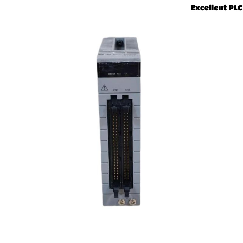
ADV561 Digital Output Module Overview
The ADV561 is a 64-channel isolated digital output module that provides current-sink transistor outputs operating at 24 VDC. It supports high-density output applications, pulse-width output functions, time-proportioning control, and dual-redundant configurations in Yokogawa FIO systems. The module is suitable for process automation applications requiring fast, reliable, and continuous digital output control. :contentReference[oaicite:0]{index=0}
Key Features
- 64 isolated digital output channels
- 24 VDC current-sink transistor outputs
- Supports pulse-width output
- Supports time-proportioning output
- Dual-redundant system compatibility
- High-density field wiring capability
Typical Industrial Applications
- Solenoid valve control
- Relay output control
- Motor starter circuits
- Process shutdown systems
- Alarm annunciators
- Pump sequencing
Installation Planning
Before installation, verify the latest engineering documentation to ensure every output channel corresponds to the approved I/O assignment.
- Review loop drawings
- Verify terminal schedules
- Confirm cable identification
- Prepare commissioning records
- Inspect cabinet layout
Hardware Inspection
- Verify module model number
- Inspect housing integrity
- Check connectors
- Inspect terminal assemblies
- Verify locking clips
Installation Environment
- Maintain adequate ventilation
- Avoid excessive humidity
- Minimize vibration
- Separate signal and power wiring
- Maintain proper cabinet grounding
External Power Supply Verification
- Measure 24 VDC supply voltage
- Verify voltage stability
- Inspect protection fuses
- Confirm polarity
- Verify common return wiring
Module Installation Procedure
- Disconnect cabinet power.
- Insert the ADV561 into the designated slot.
- Secure the retaining mechanism.
- Connect the dedicated output cable.
- Verify connector engagement.
- Restore cabinet power.
ADV561 Wiring Installation Guide
Proper cable installation significantly improves long-term reliability and simplifies future maintenance activities.
- Separate output wiring from AC cables
- Label all output channels
- Verify cable continuity
- Inspect insulation quality
- Confirm terminal tightening torque
Grounding and Shielding
- Use single-point grounding
- Terminate cable shields correctly
- Avoid ground loops
- Verify cabinet bonding
- Inspect grounding continuity
System Configuration
SCAN I/O MODULE
VERIFY NODE STATUS
ASSIGN OUTPUT CHANNELS
MAP PROCESS TAGS
DOWNLOAD CONFIGURATION
SAVE DATABASE
ENABLE OUTPUTS
Commissioning Procedure
- Execute manual output commands
- Verify relay operation
- Observe field device response
- Measure output voltage
- Record commissioning results
Functional Verification
- Confirm output response time
- Inspect channel indicators
- Verify field device operation
- Review controller diagnostics
- Test every output channel
Preventive Maintenance
- Inspect terminals every six months
- Measure output voltage periodically
- Review diagnostic history
- Verify cabinet grounding annually
- Maintain controller backups
Practical Commissioning Case
During commissioning of a pharmaceutical production line, several dosing valves connected to an ADV561 Digital Output Module failed to respond after startup.
Controller diagnostics confirmed normal communication, while voltage measured at the module output terminals remained stable at approximately 24 VDC.
Further investigation revealed that one section of the dedicated output cable had been pinched during cabinet assembly, creating intermittent conductor resistance and reducing voltage delivered to the field devices.
After replacing the damaged cable:
- All 64 output channels operated normally.
- Valve response became stable.
- No additional controller alarms occurred.
- System commissioning was completed successfully.
FAQ
How many output channels does the ADV561 provide?
The ADV561 provides 64 isolated current-sink digital output channels operating at 24 VDC. :contentReference[oaicite:1]{index=1}
Does the ADV561 support redundant systems?
Yes. The module supports dual-redundant configurations when installed in compatible Yokogawa FIO control systems. :contentReference[oaicite:2]{index=2}
What should be verified before commissioning?
Engineers should verify field wiring, external power supplies, controller configuration, output assignments, grounding, and functional operation of every connected device before placing the system into normal service.
Summary: Successful installation of the Yokogawa ADV561 Digital Output Module depends on proper engineering planning, accurate field wiring, stable 24 VDC power distribution, effective grounding, and comprehensive commissioning procedures that validate all 64 output channels under actual operating conditions.