

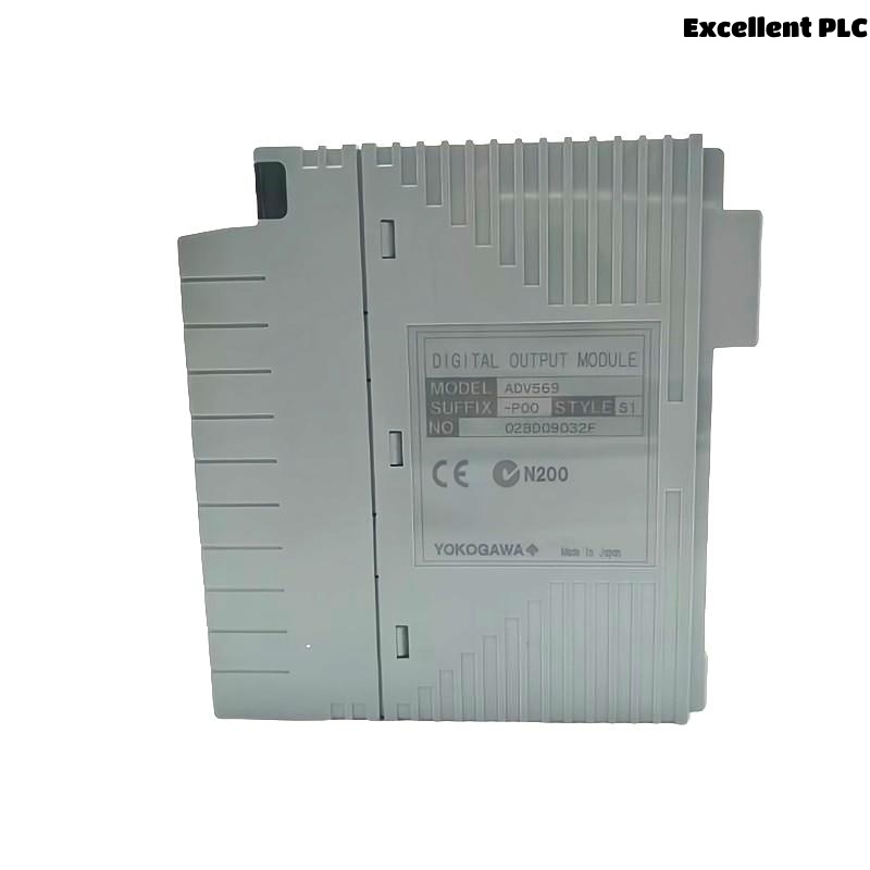
The Yokogawa ADV569 Digital I/O Module is a high-density 64-channel digital output module designed for Yokogawa CENTUM-ST compatible ST7 systems. It provides isolated transistor outputs with a common negative terminal for every 16 channels, making it suitable for large-scale industrial automation applications. Proper installation, wiring, setup, and commissioning ensure reliable field control while minimizing maintenance and downtime.
Contents
- 1. ADV569 Digital I/O Module Overview
- 2. Main Features
- 3. Typical Industrial Applications
- 4. Installation Planning
- 5. Hardware Inspection
- 6. Installation Environment
- 7. Power Supply Verification
- 8. Module Installation Procedure
- 9. ADV569 Wiring Installation Guide
- 10. Grounding and Shielding
- 11. System Configuration
- 12. Commissioning Procedure
- 13. Functional Verification
- 14. Preventive Maintenance
- 15. Practical Commissioning Case
- 16. FAQ
ADV569 Digital I/O Module Overview
The ADV569 is a 64-channel digital output module that uses isolated transistor outputs with a common negative terminal for every 16 channels. It supports pulse-width and time-proportional output functions, making it suitable for process control applications requiring accurate discrete signal switching. The module connects through a dedicated KS9 cable and is compatible with Yokogawa ST7 systems. :contentReference[oaicite:0]{index=0}
Main Features
- 64 isolated digital output channels
- Common negative every 16 channels
- 24 VDC transistor outputs
- Pulse-width output capability
- Time-proportional output function
- Compatible with ST7 systems
Typical Industrial Applications
- Solenoid valve control
- Relay output circuits
- Motor starter control
- Alarm annunciation systems
- Pump sequencing
- Process shutdown logic
Installation Planning
Successful installation begins with engineering verification before cabinet work starts.
- Review loop drawings
- Verify I/O allocation
- Check terminal schedules
- Confirm cable routing
- Prepare commissioning records
Hardware Inspection
- Verify module model number
- Inspect housing condition
- Check connectors
- Inspect cable interfaces
- Verify locking mechanism
Installation Environment
- Maintain cabinet ventilation
- Avoid excessive humidity
- Reduce vibration exposure
- Separate signal and power wiring
- Maintain proper grounding
Power Supply Verification
- Measure 24 VDC supply voltage
- Verify polarity
- Inspect protective fuses
- Confirm voltage stability
- Verify common return wiring
Module Installation Procedure
- Disconnect cabinet power.
- Install the ADV569 module into the designated ST7 slot.
- Secure the retaining mechanism.
- Connect the KS9 dedicated cable.
- Inspect connector engagement.
- Restore cabinet power.
ADV569 Wiring Installation Guide
Correct wiring reduces commissioning time and simplifies future maintenance activities.
- Separate output cables from AC power cables
- Label all output channels
- Verify cable continuity
- Inspect insulation resistance
- Confirm terminal tightening torque
Grounding and Shielding
- Use single-point grounding
- Terminate shields correctly
- Avoid ground loops
- Verify cabinet bonding
- Inspect earth continuity
System Configuration
SCAN MODULE
VERIFY NODE STATUS
ASSIGN OUTPUT CHANNELS
MAP PROCESS TAGS
DOWNLOAD CONFIGURATION
SAVE DATABASE
ENABLE OUTPUTS
Commissioning Procedure
- Issue manual output commands
- Verify relay operation
- Observe field equipment
- Measure output voltage
- Document commissioning results
Functional Verification
- Confirm output response
- Inspect output indicators
- Verify field device operation
- Review controller diagnostics
- Test all 64 output channels
Preventive Maintenance
- Inspect terminals every six months
- Measure output voltage regularly
- Review diagnostic history
- Verify grounding annually
- Maintain configuration backups
Practical Commissioning Case
During startup of a refinery utility system, twelve solenoid valves controlled by an ADV569 module failed to operate after commissioning.
Controller diagnostics showed normal communication, and voltage at the module terminals measured approximately 24 VDC. However, field measurements at the valve terminals indicated significant voltage loss.
Engineers discovered an incorrectly terminated common negative conductor affecting one 16-channel output group.
After correcting the wiring:
- All affected outputs responded normally.
- Field voltage recovered to nominal values.
- No hardware replacement was necessary.
- The system completed commissioning successfully.
FAQ
How many output channels does the ADV569 provide?
The ADV569 provides 64 isolated transistor output channels arranged with a common negative terminal for every 16 channels. :contentReference[oaicite:1]{index=1}
Does the ADV569 support pulse-width output?
Yes. The module supports pulse-width and time-proportional output functions for compatible control applications. :contentReference[oaicite:2]{index=2}
What external cable is used?
The module connects to field wiring through the dedicated KS9 connection cable specified for ST7-compatible systems. :contentReference[oaicite:3]{index=3}
Summary: Proper installation of the Yokogawa ADV569 Digital I/O Module requires careful engineering preparation, correct field wiring, stable 24 VDC power distribution, reliable grounding, and comprehensive commissioning procedures to ensure dependable operation across all 64 digital output channels.