

The Yokogawa ADV851 Digital I/O Module is a hybrid field interface module that combines 16 digital input channels and 16 digital output channels in a single unit. Designed for Yokogawa FIO-based control systems, it supports 24 VDC discrete signals, reduces cabinet space, simplifies field wiring, and provides reliable monitoring and control for industrial automation applications. Proper installation, setup, wiring, and commissioning ensure long-term operational stability and high system availability.
Contents
- 1. ADV851 Digital I/O Module Overview
- 2. Main Features
- 3. Typical Industrial Applications
- 4. Installation Planning
- 5. Hardware Inspection
- 6. Installation Environment
- 7. Power Supply Verification
- 8. Module Installation Procedure
- 9. ADV851 Wiring Installation Guide
- 10. Grounding and Shielding
- 11. System Configuration
- 12. Commissioning Procedure
- 13. Functional Verification
- 14. Preventive Maintenance
- 15. Practical Commissioning Case
- 16. Frequently Asked Questions
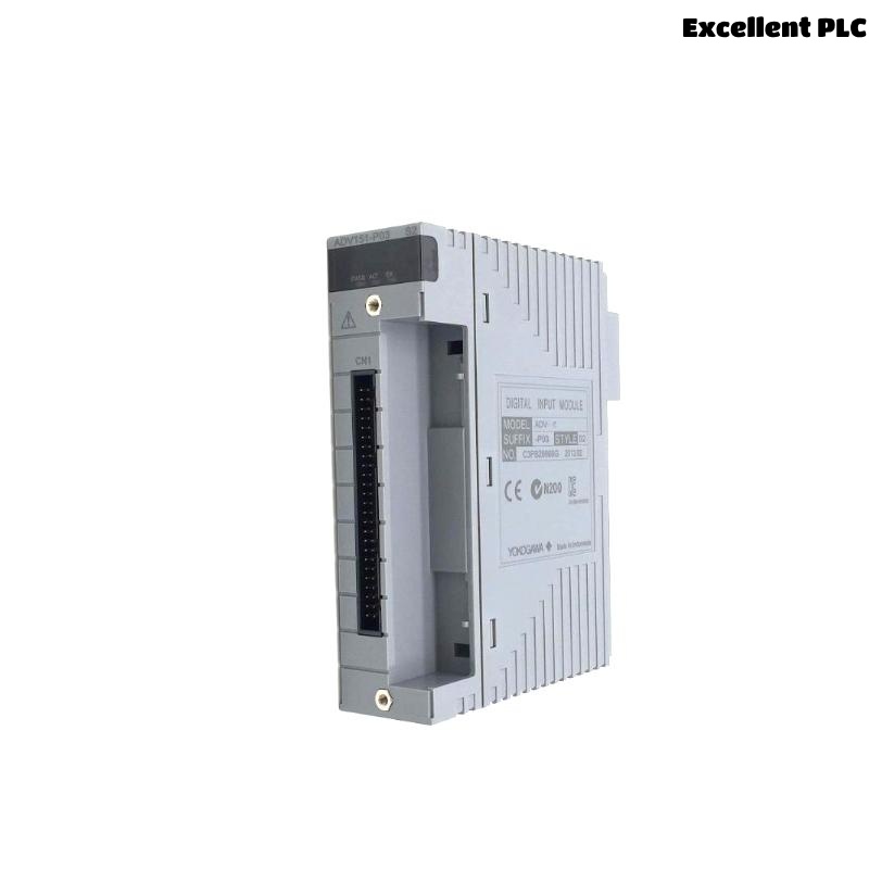
ADV851 Digital I/O Module Overview
The ADV851 integrates 16 isolated digital input channels and 16 isolated transistor digital output channels within one module. Operating with 24 VDC field signals, it is widely used in Yokogawa CENTUM VP and CENTUM CS systems where both monitoring and control functions are required in the same cabinet location. Combining input and output functions helps reduce module count, simplify wiring, and improve installation efficiency. The module is compatible with redundant FIO architectures and supports high-speed signal processing for industrial control applications.
Main Features
- 16 digital input channels
- 16 digital output channels
- 24 VDC operation
- Hybrid input/output design
- Compact cabinet installation
- Compatible with Yokogawa FIO systems
Typical Industrial Applications
- Valve monitoring and control
- Motor start/stop circuits
- Relay interface panels
- Pump sequencing systems
- Packaging machinery
- Process automation skids
Installation Planning
Engineering documents should be reviewed before installation to ensure all field signals match the approved I/O allocation.
- Verify loop diagrams
- Review terminal schedules
- Confirm cable routing
- Prepare commissioning records
- Inspect cabinet layout
Hardware Inspection
- Confirm module identification
- Inspect housing condition
- Verify connector integrity
- Inspect terminal assemblies
- Check retaining mechanism
Installation Environment
- Maintain adequate cabinet ventilation
- Avoid excessive humidity
- Reduce vibration exposure
- Separate signal and power wiring
- Maintain effective grounding
Power Supply Verification
- Measure 24 VDC supply voltage
- Verify polarity
- Inspect protective fuses
- Confirm voltage stability
- Verify common return wiring
Module Installation Procedure
- Switch off cabinet power.
- Insert the ADV851 into the designated FIO slot.
- Secure the locking mechanism.
- Connect the field terminal assembly.
- Verify connector engagement.
- Restore cabinet power.
ADV851 Wiring Installation Guide
Proper wiring practices improve signal integrity and simplify future maintenance.
- Separate I/O wiring from AC power cables
- Label every input and output channel
- Verify cable continuity
- Inspect insulation resistance
- Confirm terminal tightening torque
Grounding and Shielding
- Use single-point grounding
- Terminate cable shields correctly
- Avoid ground loops
- Verify cabinet bonding
- Inspect grounding continuity
System Configuration
SCAN I/O MODULE
VERIFY NODE STATUS
ASSIGN INPUT CHANNELS
ASSIGN OUTPUT CHANNELS
MAP PROCESS TAGS
DOWNLOAD CONFIGURATION
SAVE DATABASE
Commissioning Procedure
- Verify input status changes
- Execute output switching tests
- Measure field voltage
- Observe connected equipment
- Record commissioning results
Functional Verification
- Confirm all input signals
- Verify all output channels
- Review controller diagnostics
- Check communication status
- Validate complete I/O operation
Preventive Maintenance
- Inspect wiring every six months
- Check terminal tightness
- Review diagnostic history
- Verify cabinet grounding annually
- Maintain engineering backups
Practical Commissioning Case
During commissioning of a water treatment control system, operators reported that several digital inputs updated correctly while associated output commands failed to energize the connected solenoid valves.
Controller diagnostics confirmed that the ADV851 communicated normally with the FIO network. Input channels responded correctly, but field measurements revealed that the external 24 VDC output supply had not been connected after cabinet maintenance.
After restoring the external power supply:
- All digital outputs operated normally.
- Input status remained stable.
- No controller alarms were generated.
- Commissioning was completed successfully without replacing the module.
Frequently Asked Questions
What I/O configuration does the ADV851 provide?
The ADV851 combines 16 digital input channels and 16 digital output channels operating at 24 VDC within a single module, making it suitable for compact mixed I/O applications. :contentReference[oaicite:0]{index=0}
Which control systems support the ADV851?
The module is designed for Yokogawa FIO-based systems, including CENTUM VP and CENTUM CS platforms. :contentReference[oaicite:1]{index=1}
What should be verified before commissioning?
Verify field wiring, external 24 VDC power supplies, controller configuration, grounding, and proper operation of every input and output channel before placing the system into service.
Summary: Successful installation of the Yokogawa ADV851 Digital I/O Module depends on accurate engineering preparation, correct wiring, stable power supplies, reliable grounding, and comprehensive commissioning procedures that validate both digital input and digital output functions under actual operating conditions.