

The Yokogawa AIP502 V-Net Coupler Module is a high-performance communication interface used in Yokogawa CENTUM CS and CENTUM VP Distributed Control Systems (DCS). It provides the coupling function between Field Control Units (FCUs) and the V-Net real-time control network, enabling deterministic data exchange across controllers, operator stations, engineering stations, and system gateways. The AIP502 supports high-speed communication and redundant network configurations, making it a critical component for system reliability and plant-wide control integration. Proper installation, cable routing, configuration, and commissioning are essential to ensure stable and fault-tolerant operation.
Contents
- 1. Product Overview
- 2. Main Features
- 3. Typical Applications
- 4. Installation Preparation
- 5. Hardware Inspection
- 6. Module Installation
- 7. Communication Switch Configuration
- 8. V-Net Cabling
- 9. Network Configuration
- 10. Commissioning Procedure
- 11. Functional Testing
- 12. Redundancy Verification
- 13. Preventive Maintenance
- 14. Practical Installation Case
- 15. Frequently Asked Questions
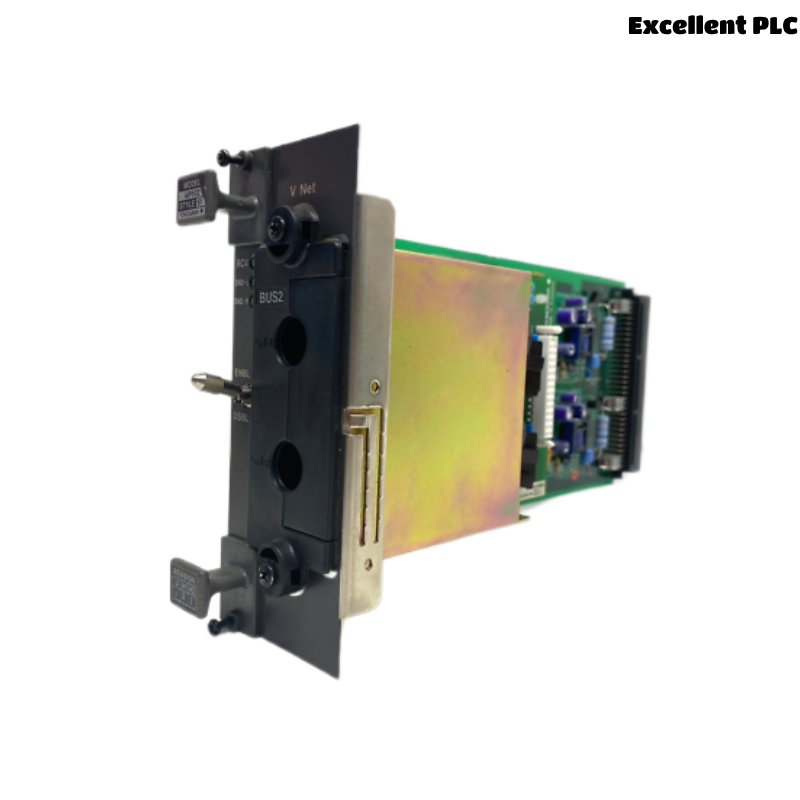
Product Overview
The AIP502 acts as a V-Net coupler interface that connects FCUs to the Yokogawa control network backbone. It ensures real-time deterministic communication required for process control applications in large-scale industrial plants.
Main Features
- High-speed V-Net communication interface
- Supports redundant network architecture
- Deterministic real-time data transmission
- Industrial-grade reliability for 24/7 operation
- Seamless integration with CENTUM CS / VP systems
- Stable communication under high-load conditions
- Modular replacement and maintenance design
- Fault-tolerant network operation capability
Typical Applications
- Field Control Units (FCU) in DCS systems
- Oil and gas production facilities
- Petrochemical plants
- Power generation systems
- Refining and chemical process control
- Large-scale industrial automation networks
Installation Preparation
- Review V-Net network topology and redundancy design
- Confirm FCU compatibility with AIP502
- Prepare ESD protection equipment
- Verify cable routing paths for V-Net trunk lines
- Ensure maintenance window for safe installation
Hardware Inspection
- Verify module model: AIP502
- Inspect connectors for physical damage
- Check backplane interface pins
- Confirm LED indicators are intact
- Verify correct hardware revision and labeling
Module Installation
- Shut down FCU or follow safe maintenance procedure
- Ensure anti-static protection (ESD strap required)
- Insert AIP502 firmly into designated slot
- Secure mounting screws properly
- Verify full backplane engagement
Communication Switch Configuration
- Set module switch to DSBL during installation
- After installation and cable connection, switch to ENBL
- Ensure switch position is verified before commissioning
- Incorrect switch state may prevent V-Net participation
V-Net Cabling
- Connect V-Net trunk and branch cables securely
- Avoid tight bends or mechanical stress on cables
- Maintain separation from power and high-noise lines
- Ensure correct connector orientation and locking
- Verify redundancy path (if dual network is used)
Network Configuration
- Assign correct FCU station address
- Verify V-Net domain settings
- Enable redundant communication paths if required
- Synchronize configuration with engineering station
- Confirm controller registration in network database
Commissioning Procedure
VERIFY INSTALLATION
CHECK SWITCH POSITION (ENBL)
CONNECT V-NET CABLES
POWER UP FCU
VERIFY NODE DETECTION
CONFIRM REDUNDANCY STATUS
CHECK COMMUNICATION LOGS
START NORMAL OPERATION
Functional Testing
- Verify FCU visibility on V-Net
- Confirm operator station communication
- Test real-time data updates
- Check alarm and event transmission
- Validate network latency stability
Redundancy Verification
- Simulate primary network path failure
- Confirm automatic switchover to secondary path
- Verify no data loss during switch
- Check synchronization between channels
Preventive Maintenance
- Inspect V-Net connectors regularly
- Verify switch position during maintenance cycles
- Clean connector contacts periodically
- Check cable aging and shielding integrity
- Test redundancy paths during shutdowns
Practical Installation Case
During a refinery control system upgrade, an AIP502 was installed but the FCU did not appear on the V-Net network after startup.
Investigation revealed the communication switch was left in DSBL position after installation.
After switching to ENBL:
- The FCU immediately appeared on the V-Net
- Operator stations restored communication
- Redundant paths activated correctly
- No further network alarms occurred
Frequently Asked Questions
What is the main function of the AIP502?
It connects FCUs to the Yokogawa V-Net control network for real-time distributed control communication.
Why is the ENBL/DSBL switch important?
DSBL isolates the module during installation; ENBL enables active participation in the V-Net network.
What should be checked after installation?
Verify network detection, communication stability, redundancy operation, and alarm-free system status.
Summary
The Yokogawa AIP502 V-Net Coupler Module requires correct installation, proper switch configuration, secure cabling, accurate network setup, and full communication testing. Following these procedures ensures stable real-time V-Net communication, reliable redundancy, and high availability in industrial control systems.