

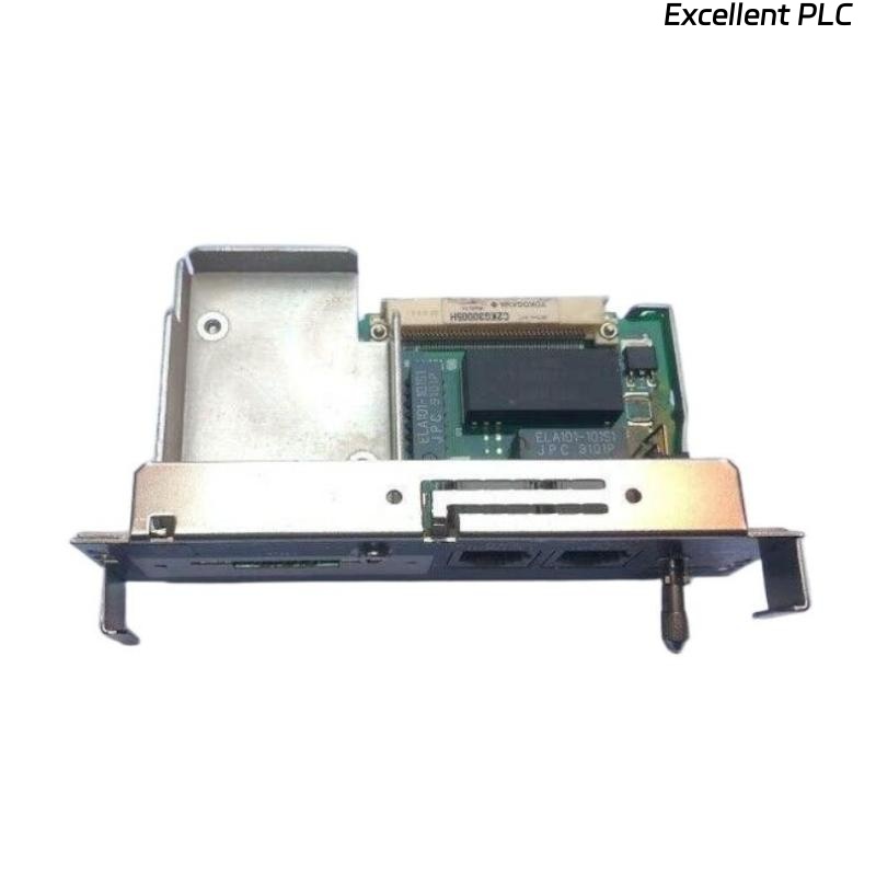
The Yokogawa AIP504-10 V-Net Coupler Unit is a communication interface installed between the processor module and the Yokogawa V-Net control network in ProSafe-RS Safety Control Stations (SCS). Its primary functions are signal isolation, signal level conversion, and reliable communication between the processor module and the dual-redundant V-Net buses. Under normal operation, the communication switch should remain in the ENBL position, allowing the processor to communicate with the V-Net. Communication failures involving the AIP504-10 may result in processor isolation, controller communication loss, redundancy degradation, or safety system alarms. A systematic troubleshooting procedure helps maintenance engineers identify faults quickly and restore reliable network communication.
Contents
- 1. Understanding V-Net Communication Faults
- 2. Common Failure Symptoms
- 3. Typical Causes of Communication Problems
- 4. Initial Hardware Inspection
- 5. Communication Switch Verification
- 6. V-Net Cable Diagnostics
- 7. Processor Interface Verification
- 8. Diagnostic Analysis
- 9. Recommended Troubleshooting Workflow
- 10. Corrective Actions
- 11. Communication Recovery Verification
- 12. Preventive Maintenance
- 13. Real Industrial Maintenance Case
- 14. Frequently Asked Questions
Understanding V-Net Communication Faults
The AIP504-10 performs signal isolation and level conversion between the processor module and the dual-redundant V-Net communication buses. Two coupler units are normally installed to support Bus 1 and Bus 2 redundancy. Communication failures may interrupt safety controller operation or disable network redundancy.
Common Failure Symptoms
- Safety controller cannot communicate with the V-Net.
- Processor module appears offline.
- Loss of one redundant communication channel.
- Network communication alarms.
- Engineering station cannot reach the controller.
- Operator station loses controller visibility.
- Status LEDs indicate abnormal communication.
- Communication repeatedly disconnects and reconnects.
Typical Causes of Communication Problems
- Communication switch left in DSBL position.
- Loose V-Net branch connector.
- Damaged V-Net coupler cable.
- Poor processor module connection.
- Incorrect network configuration.
- Power supply instability.
- Electromagnetic interference.
- Internal coupler hardware failure.
Initial Hardware Inspection
- Verify the module is fully inserted.
- Inspect the branch connector.
- Check the V-Net coupler cable.
- Inspect processor module connectors.
- Verify LED indicator status.
Communication Switch Verification
- Confirm the switch is in the ENBL position during normal operation.
- Ensure the switch is not accidentally left at DSBL after maintenance.
- Operate the locking switch correctly before changing its position.
- Verify communication recovery after enabling the module.
V-Net Cable Diagnostics
- Inspect branch connector engagement.
- Verify cable continuity.
- Check connector locking.
- Inspect cable shielding.
- Replace damaged communication cables.
Processor Interface Verification
- Verify processor module seating.
- Inspect the coupler cable between processor and AIP504-10.
- Confirm processor startup.
- Review processor communication diagnostics.
- Verify synchronization with the V-Net.
Diagnostic Analysis
| Observed Condition | Possible Cause |
|---|---|
| No communication | Communication switch in DSBL position |
| Controller offline | Loose coupler cable or processor connection |
| Bus redundancy lost | Secondary coupler or branch cable fault |
| Intermittent communication | Poor connector contact or cable damage |
| Communication alarms | Network interruption or processor interface fault |
Recommended Troubleshooting Workflow
VERIFY POWER
CHECK MODULE INSTALLATION
VERIFY ENBL SWITCH POSITION
INSPECT PROCESSOR CONNECTION
CHECK V-NET CABLES
REVIEW SYSTEM DIAGNOSTICS
VERIFY REDUNDANT BUS STATUS
RESTORE COMMUNICATION
VERIFY NETWORK OPERATION
MONITOR SYSTEM STABILITY
Corrective Actions
- Move the communication switch to ENBL.
- Reconnect loose branch connectors.
- Replace damaged coupler cables.
- Correct network configuration.
- Restore stable power supplies.
- Reseat the processor module if necessary.
- Replace the AIP504-10 only after confirming internal hardware failure.
Communication Recovery Verification
- Verify controller appears on the V-Net.
- Confirm communication with engineering stations.
- Verify operator station connectivity.
- Test redundant Bus 1 and Bus 2 operation.
- Confirm communication alarms have cleared.
Preventive Maintenance
- Inspect connectors during scheduled maintenance.
- Verify ENBL switch position before returning to service.
- Clean communication connectors periodically.
- Test redundant communication channels.
- Review diagnostic logs regularly.
Real Industrial Maintenance Case
During a scheduled shutdown of a ProSafe-RS Safety Control Station, engineers replaced an AIP504-10 V-Net Coupler Unit.
After startup, the controller remained offline because the communication switch was inadvertently left in the DSBL position.
After unlocking the switch and moving it to ENBL:
- The processor immediately joined the V-Net.
- Both redundant communication buses became operational.
- Safety communication alarms cleared automatically.
- The Safety Control Station resumed normal operation without further issues.
Frequently Asked Questions
What is the primary function of the AIP504-10?
The AIP504-10 isolates communication signals, performs signal level conversion, and connects the processor module to the dual-redundant Yokogawa V-Net communication network.
Why is the ENBL/DSBL switch important?
The ENBL position connects the processor module to the V-Net for normal operation, while the DSBL position disconnects the processor from the communication bus for maintenance.
When should the AIP504-10 be replaced?
The unit should only be replaced after confirming correct switch position, stable power, intact cables, proper processor connections, and persistent communication failure that indicates an internal hardware fault.
Summary
Effective troubleshooting of the Yokogawa AIP504-10 V-Net Coupler Unit requires systematic inspection of the communication switch, processor interface, V-Net cables, redundant communication paths, and diagnostic information. Following a structured troubleshooting process minimizes downtime, restores reliable V-Net communication, and maintains the high availability required for industrial safety control systems.