

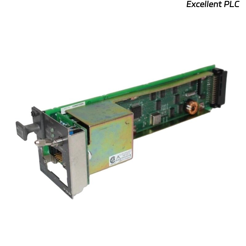
The Yokogawa AIP512 V-Net Coupler Module is a communication interface module used in Yokogawa CENTUM VP Distributed Control Systems (DCS). It provides the communication bridge between the Field Control Unit (FCU) and the V-Net control network, enabling deterministic, high-speed data exchange between controllers, operator stations, engineering stations, historians, and gateway devices. The AIP512 supports redundant V-Net communication, providing high availability and fault tolerance required for mission-critical industrial automation systems. Proper installation, network configuration, and commissioning are essential to ensure reliable communication and long-term system stability.
Contents
- 1. Product Overview
- 2. Main Features
- 3. Typical Applications
- 4. Installation Preparation
- 5. Hardware Inspection
- 6. Module Installation
- 7. V-Net Cable Connections
- 8. Network Configuration
- 9. Commissioning Procedure
- 10. Functional Verification
- 11. Redundancy Verification
- 12. Preventive Maintenance
- 13. Practical Installation Case
- 14. Frequently Asked Questions
Product Overview
The AIP512 serves as the communication interface between the FCU and the Yokogawa V-Net control network. It enables reliable real-time communication with remote I/O segments and distributed control components while supporting redundant communication paths to maximize system availability.
Main Features
- High-speed V-Net communication interface
- Support for redundant V-Net architecture
- Deterministic real-time data transmission
- Industrial-grade reliability
- Fast communication with remote I/O systems
- Integrated diagnostic status indicators
- Modular design for simplified maintenance
- Continuous 24-hour industrial operation
Typical Applications
- CENTUM VP Field Control Units
- Distributed Control Systems (DCS)
- Remote I/O communication networks
- Oil and gas facilities
- Petrochemical plants
- Power generation systems
- Large-scale process automation
Installation Preparation
- Review network architecture drawings.
- Verify module compatibility with the FCU.
- Prepare ESD protection equipment.
- Confirm V-Net cable routing.
- Schedule an approved maintenance window.
Hardware Inspection
- Verify the AIP512 model number.
- Inspect the module housing for damage.
- Check backplane connectors.
- Inspect communication ports.
- Verify LED indicators.
Module Installation
- Place the controller in a safe maintenance state.
- Wear an anti-static wrist strap.
- Insert the AIP512 completely into the designated slot.
- Secure the retaining screws.
- Verify proper engagement with the backplane.
- Connect the required communication cables.
V-Net Cable Connections
- Connect the primary V-Net communication cable.
- Connect the redundant communication cable if installed.
- Secure all connectors.
- Maintain the specified cable bending radius.
- Route communication cables separately from power wiring.
Network Configuration
- Assign the correct controller node address.
- Configure the V-Net communication domain.
- Enable redundant communication channels.
- Synchronize engineering database parameters.
- Verify controller registration on the network.
Commissioning Procedure
VERIFY MODULE INSTALLATION
CHECK CABLE CONNECTIONS
POWER ON THE FCU
VERIFY MODULE DETECTION
CHECK V-NET COMMUNICATION
VERIFY REDUNDANCY
TEST DATA TRANSMISSION
PLACE SYSTEM INTO OPERATION
Functional Verification
- Verify controller visibility on V-Net.
- Confirm communication with operator stations.
- Verify engineering station connectivity.
- Test process data updates.
- Review diagnostic messages.
Redundancy Verification
- Verify primary communication path.
- Verify secondary communication path.
- Simulate a communication path failure.
- Confirm automatic switchover.
- Verify uninterrupted controller communication.
Preventive Maintenance
- Inspect communication connectors regularly.
- Clean connector contacts during maintenance.
- Verify cable integrity.
- Review communication diagnostic logs.
- Perform periodic redundancy testing.
Practical Installation Case
During the expansion of a petrochemical DCS network, an AIP512 module was installed in a new Field Control Unit to connect additional Remote I/O nodes.
After startup, the engineering station could not detect the new controller because one V-Net connector was not fully engaged.
After securing the connector:
- The controller immediately appeared on the V-Net.
- Operator stations displayed live process values.
- Engineering stations established stable communication.
- Redundant communication paths operated normally.
Frequently Asked Questions
What is the primary function of the AIP512?
The AIP512 provides the communication interface between the Field Control Unit and the Yokogawa V-Net network, supporting high-speed communication with remote I/O and distributed control components.
Does the AIP512 support redundant communication?
Yes. The module supports redundant V-Net communication paths to improve system availability and communication reliability.
What should be verified after installation?
Verify controller detection, network communication, engineering station access, operator station connectivity, redundant communication operation, and the absence of communication alarms.
Summary
Proper installation of the Yokogawa AIP512 V-Net Coupler Module requires secure module mounting, correct V-Net cable connections, accurate network configuration, comprehensive communication testing, and redundancy verification. Following these procedures ensures reliable real-time communication, high system availability, and dependable operation of Yokogawa CENTUM VP distributed control systems.