 Excellent PLC


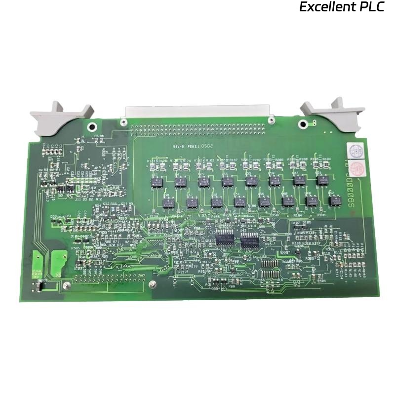
The Yokogawa AMM11 Voltage Input Multiplexer Module is an analog signal acquisition module used in Yokogawa CENTUM CS and CENTUM VP Distributed Control Systems (DCS). It multiplexes multiple voltage input channels into a shared acquisition circuit, enabling efficient monitoring of process variables from transmitters, analyzers, sensors, and other field instruments. Stable operation depends on proper wiring, accurate configuration, clean analog signals, and healthy module hardware. Faults such as incorrect measurements, unstable signals, channel failures, or communication alarms are typically caused by wiring errors, incorrect input configuration, grounding problems, electrical interference, or module hardware failures. This guide provides a systematic troubleshooting procedure for diagnosing AMM11 faults and restoring reliable analog signal acquisition.
Contents
- 1. Understanding Module Faults
- 2. Common Failure Symptoms
- 3. Typical Causes
- 4. Initial Hardware Inspection
- 5. Analog Signal Verification
- 6. Diagnostic Analysis
- 7. Recommended Troubleshooting Workflow
- 8. Corrective Actions
- 9. Functional Recovery Verification
- 10. Preventive Maintenance
- 11. Industrial Maintenance Case
- 12. Frequently Asked Questions
Understanding Module Faults
The AMM11 acquires multiple analog voltage signals through multiplexed channel scanning before transmitting digital measurement data to the controller. Reliable operation requires proper input voltage levels, secure terminal connections, correct software configuration, adequate shielding, and stable grounding. Measurement problems frequently result from loose wiring, incorrect channel assignments, excessive electrical noise, sensor failures, or damaged module circuitry. Yokogawa analog input modules are configured in software for the appropriate input ranges and require proper field wiring practices for accurate measurements.
Common Failure Symptoms
- No analog input value displayed.
- Input value remains fixed.
- Unstable or fluctuating measurements.
- Channel over-range or under-range alarms.
- Multiple channels reading incorrectly.
- Abnormal engineering values.
- Intermittent channel failures.
- Module diagnostic alarms.
Typical Causes
- Incorrect voltage input wiring.
- Loose terminal connections.
- Improper input range configuration.
- Damaged field sensor.
- Broken signal cable.
- Poor shielding or grounding.
- Electrical interference.
- Internal AMM11 hardware failure.
Initial Hardware Inspection
- Verify the AMM11 is fully inserted into the I/O base.
- Inspect terminal block connections.
- Check module locking mechanisms.
- Verify cabinet power supply.
- Inspect module status indicators.
Analog Signal Verification
- Measure field input voltage using a calibrated multimeter.
- Verify channel polarity.
- Confirm configured input range matches the field device.
- Inspect cable insulation.
- Verify shield grounding at the recommended location.
- Check transmitter operation independently.
Diagnostic Analysis
| Observed Condition | Possible Diagnosis |
|---|---|
| No input value | Broken wiring, sensor failure, or module fault |
| Constant reading | Incorrect wiring or failed field transmitter |
| Fluctuating signal | Electrical noise or poor grounding |
| Over-range alarm | Input voltage exceeds configured range |
| Multiple channel faults | Power supply issue or module hardware failure |
Recommended Troubleshooting Workflow
CHECK MODULE STATUS
VERIFY POWER SUPPLY
INSPECT FIELD WIRING
MEASURE INPUT VOLTAGE
VERIFY CHANNEL CONFIGURATION
CHECK DIAGNOSTIC INFORMATION
VERIFY SIGNAL STABILITY
CONFIRM NORMAL OPERATION
Corrective Actions
- Reconnect loose wiring.
- Replace damaged signal cables.
- Correct software channel configuration.
- Repair or replace faulty transmitters.
- Improve cable shielding and grounding.
- Eliminate nearby sources of electromagnetic interference.
- Replace the AMM11 module if hardware diagnostics confirm failure.
Functional Recovery Verification
- Verify all configured channels respond correctly.
- Compare displayed values with calibrated test equipment.
- Confirm alarm operation.
- Review module diagnostics.
- Monitor measurement stability over an extended period.
Preventive Maintenance
- Inspect field wiring during scheduled maintenance.
- Tighten terminal screws as required.
- Verify cable shielding integrity.
- Check cabinet grounding.
- Review module diagnostic logs periodically.
- Perform routine instrument calibration verification.
Industrial Maintenance Case
At a petrochemical processing facility, several pressure transmitter signals connected to an AMM11 module began exhibiting unstable readings after a maintenance shutdown.
Inspection found that the analog signal cable shields had been grounded at both ends during cable replacement, creating a ground loop that introduced electrical noise. After correcting the shielding method and verifying the input wiring:
- Signal fluctuations disappeared.
- All voltage channels operated within specification.
- Controller measurements matched calibrated field instruments.
- No additional analog input alarms occurred during continuous operation.
Frequently Asked Questions
Why does one analog channel always read zero?
Possible causes include an open circuit, incorrect terminal wiring, failed field transmitter, incorrect channel configuration, or an input circuit fault on the module.
Why are several channels unstable simultaneously?
Multiple unstable channels often indicate grounding problems, electromagnetic interference, shared wiring issues, unstable power supplies, or a developing module hardware fault.
What should be checked before replacing the AMM11?
Verify field transmitter operation, input voltage, terminal wiring, software configuration, cable shielding, grounding quality, controller diagnostics, and power supply stability before concluding that the module itself has failed. Proper polarity, wiring integrity, and configured input ranges should always be confirmed first.
Summary
Effective troubleshooting of the Yokogawa AMM11 Voltage Input Multiplexer Module requires systematic verification of module installation, analog wiring, signal integrity, channel configuration, grounding, shielding, and controller diagnostics. Routine preventive maintenance, accurate field calibration, and prompt correction of wiring or configuration issues help ensure reliable long-term analog signal acquisition and stable operation in Yokogawa CENTUM Distributed Control Systems.