 Excellent PLC


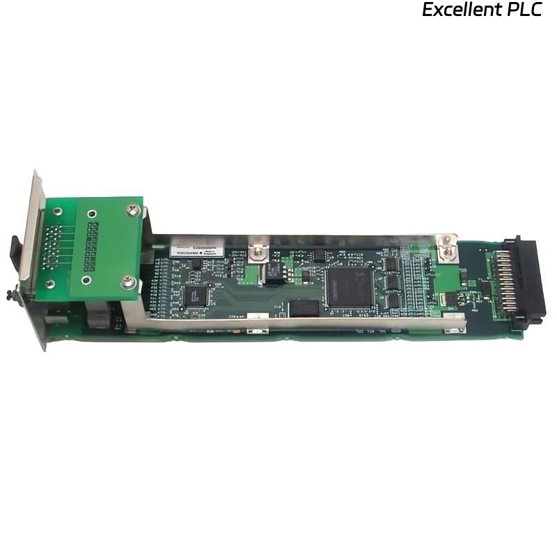
The Yokogawa AIP532 ESB Bus Coupler Unit is the ESB bus master communication interface used in Yokogawa CENTUM VP and ProSafe-RS control systems. It connects the Field Control Unit (FCU) processor to ESB Bus Node Units, providing deterministic communication with remote I/O modules over dual-redundant ESB buses. Because the AIP532 serves as the communication gateway for distributed I/O, failures can result in loss of field signals, remote I/O communication interruptions, controller alarms, or degradation of redundant communication. A structured troubleshooting procedure enables maintenance engineers to quickly isolate communication faults and restore normal system operation.
Contents
- 1. Understanding ESB Bus Communication Faults
- 2. Common Failure Symptoms
- 3. Typical Causes of Communication Failures
- 4. Initial Hardware Inspection
- 5. Power Supply Verification
- 6. ESB Bus Cable Diagnostics
- 7. ESB Bus Configuration Verification
- 8. Diagnostic Analysis
- 9. Recommended Troubleshooting Workflow
- 10. Corrective Actions
- 11. Communication Recovery Verification
- 12. Preventive Maintenance
- 13. Real Industrial Maintenance Case
- 14. Frequently Asked Questions
Understanding ESB Bus Communication Faults
The AIP532 operates as the master interface for the ESB bus, exchanging cyclic process data between the FCU and remote ESB Bus Node Units. Most communication problems originate from cable damage, loose connectors, configuration mismatches, node failures, or power instability rather than failure of the AIP532 hardware itself.
Common Failure Symptoms
- Remote I/O stations become unavailable.
- Input or output signals are lost.
- ESB bus communication alarms appear.
- Engineering station reports node communication failure.
- Intermittent remote I/O updates.
- Redundant ESB bus path becomes inactive.
- Field Control Unit reports communication diagnostics.
- Status LEDs indicate abnormal operation.
Typical Causes of Communication Failures
- Loose ESB bus communication connectors.
- Damaged communication cable.
- Incorrect node address configuration.
- Failure of an ESB Bus Node Unit.
- Power supply instability.
- Backplane connection problems.
- Electromagnetic interference.
- Internal AIP532 hardware failure.
Initial Hardware Inspection
- Verify the module is fully inserted into the rack.
- Inspect backplane connectors.
- Check ESB communication connectors.
- Inspect cable locking mechanisms.
- Verify module LED indications.
Power Supply Verification
- Measure FCU supply voltage.
- Verify remote node power supplies.
- Inspect redundant power sources.
- Review power-related diagnostic alarms.
- Correct power abnormalities before communication testing.
ESB Bus Cable Diagnostics
- Verify cable continuity.
- Inspect connectors for contamination.
- Check cable shielding integrity.
- Replace damaged communication cables.
- Verify both redundant ESB communication paths.
ESB Bus Configuration Verification
- Verify ESB node addresses.
- Confirm engineering database consistency.
- Verify communication parameters.
- Check remote I/O assignment.
- Confirm redundancy configuration.
Diagnostic Analysis
| Observed Condition | Possible Diagnosis |
|---|---|
| Remote I/O offline | Communication cable disconnected or node power failure |
| Intermittent communication | Loose connector or cable degradation |
| Redundant bus unavailable | Secondary ESB communication path failure |
| Communication alarms | Configuration mismatch or network interruption |
| Missing field signals | Node communication failure or bus fault |
Recommended Troubleshooting Workflow
VERIFY POWER SUPPLIES
CHECK MODULE INSTALLATION
INSPECT ESB BUS CABLES
VERIFY NODE CONFIGURATION
CHECK REMOTE I/O STATUS
REVIEW DIAGNOSTIC LOGS
TEST REDUNDANT BUS
IMPLEMENT CORRECTIVE ACTION
VERIFY COMMUNICATION RECOVERY
MONITOR LONG-TERM OPERATION
Corrective Actions
- Reconnect loose ESB bus connectors.
- Replace damaged communication cables.
- Repair or replace faulty node units.
- Correct configuration mismatches.
- Restore stable power supplies.
- Reload controller configuration if required.
- Replace the AIP532 only after confirming internal hardware failure.
Communication Recovery Verification
- Verify all remote I/O nodes are online.
- Confirm engineering station communication.
- Verify process signal updates.
- Test redundant ESB bus switchover.
- Confirm communication alarms have cleared.
Preventive Maintenance
- Inspect ESB communication connectors regularly.
- Clean connector contacts during scheduled maintenance.
- Verify cable integrity.
- Review communication diagnostics periodically.
- Perform redundancy testing during plant shutdowns.
Real Industrial Maintenance Case
During routine maintenance at a chemical processing facility, several remote I/O stations unexpectedly went offline following controller restart.
Investigation revealed that one ESB bus communication connector on the AIP532 had not been completely tightened after maintenance.
After securing the connector:
- All remote I/O stations returned online.
- Field input and output signals recovered immediately.
- Engineering diagnostics confirmed healthy ESB communication.
- The redundant communication path resumed normal operation.
Frequently Asked Questions
Why are remote I/O stations not communicating?
The most common causes are loose ESB bus connectors, damaged communication cables, node power failures, or incorrect configuration parameters.
Can one faulty ESB node interrupt the entire network?
Depending on the network topology and the nature of the fault, a defective node or communication cable can affect downstream communication and generate controller alarms.
When should the AIP532 be replaced?
The AIP532 should only be replaced after verifying communication cables, node power supplies, ESB configuration, connector integrity, and confirming an internal hardware failure through diagnostic testing.
Summary
Effective troubleshooting of the Yokogawa AIP532 ESB Bus Coupler Unit requires systematic verification of power supplies, ESB communication cables, node configuration, remote I/O status, redundancy operation, and diagnostic information. Following a structured troubleshooting methodology minimizes process downtime, restores reliable remote I/O communication, and ensures the high availability required for Yokogawa CENTUM VP and ProSafe-RS automation systems.