 Excellent PLC


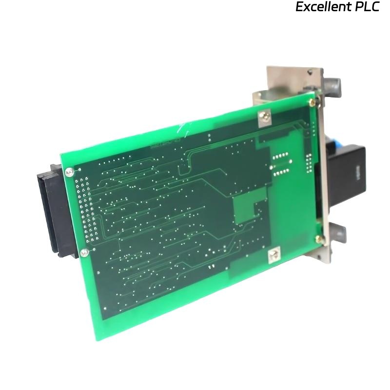
The Yokogawa AIP581 Electrical Transceiver RIO I/O Module is an electrical communication interface used in Yokogawa CENTUM VP and CENTUM CS 3000 Distributed Control Systems (DCS). It serves as the electrical transceiver for the Remote I/O (RIO) communication network, enabling deterministic, high-speed communication between the Field Control Unit (FCU) and distributed Remote I/O stations. Reliable communication through the AIP581 is essential for maintaining continuous field data acquisition and control. Communication failures involving the AIP581 can result in Remote I/O outages, missing field signals, controller alarms, or degraded plant performance. A structured troubleshooting procedure enables maintenance personnel to rapidly identify faults and restore stable communication.
Contents
- 1. Understanding RIO Communication Faults
- 2. Common Failure Symptoms
- 3. Typical Causes of Communication Failures
- 4. Initial Hardware Inspection
- 5. Power Supply Verification
- 6. Communication Wiring Diagnostics
- 7. Communication Configuration Verification
- 8. Diagnostic Analysis
- 9. Recommended Troubleshooting Workflow
- 10. Corrective Actions
- 11. Communication Recovery Verification
- 12. Preventive Maintenance
- 13. Real Industrial Maintenance Case
- 14. Frequently Asked Questions
Understanding RIO Communication Faults
The AIP581 provides the electrical communication interface between the FCU and Remote I/O stations. Most communication problems are caused by loose connectors, damaged communication cables, incorrect station addressing, grounding problems, or unstable power supplies rather than internal hardware failures.
Common Failure Symptoms
- Remote I/O station is offline.
- Controller reports communication timeout alarms.
- Engineering workstation cannot detect the Remote I/O station.
- Process input or output signals disappear.
- Intermittent communication with field devices.
- Communication error LEDs are illuminated.
- Controller diagnostic alarms occur repeatedly.
- Unexpected loss of process data updates.
Typical Causes of Communication Failures
- Loose communication connectors.
- Damaged communication cable.
- Incorrect Remote I/O station address.
- Improper cable shielding or grounding.
- Power supply instability.
- Electromagnetic interference.
- Backplane connection problems.
- Internal AIP581 hardware failure.
Initial Hardware Inspection
- Verify the module is fully seated.
- Inspect the backplane connector.
- Check communication terminals.
- Inspect cable locking mechanisms.
- Verify module status indicators.
Power Supply Verification
- Measure FCU supply voltage.
- Verify Remote I/O cabinet power supplies.
- Inspect redundant power systems if installed.
- Review controller power diagnostics.
- Correct power abnormalities before communication testing.
Communication Wiring Diagnostics
- Inspect communication cable continuity.
- Verify cable shielding is correctly grounded.
- Check connector tightness.
- Inspect cable routing for physical damage.
- Replace damaged communication cables when necessary.
Communication Configuration Verification
- Verify Remote I/O station addresses.
- Confirm controller communication parameters.
- Review engineering database configuration.
- Verify communication initialization.
- Check overall network topology consistency.
Diagnostic Analysis
| Observed Condition | Possible Diagnosis |
|---|---|
| Remote I/O offline | Communication cable disconnected or station power failure |
| Intermittent communication | Loose connector or damaged communication cable |
| Communication timeout | Incorrect station configuration or excessive electrical noise |
| Missing process signals | Remote I/O communication interruption |
| Repeated communication alarms | Unstable communication network or hardware fault |
Recommended Troubleshooting Workflow
VERIFY POWER SUPPLIES
CHECK MODULE INSTALLATION
INSPECT COMMUNICATION CABLES
VERIFY CONNECTOR TIGHTNESS
CHECK REMOTE I/O CONFIGURATION
REVIEW CONTROLLER DIAGNOSTICS
VERIFY SIGNAL COMMUNICATION
IMPLEMENT CORRECTIVE ACTION
VERIFY SYSTEM RECOVERY
MONITOR LONG-TERM OPERATION
Corrective Actions
- Reconnect loose communication connectors.
- Replace damaged communication cables.
- Correct Remote I/O addressing.
- Improve cable grounding and shielding.
- Restore stable power supplies.
- Reload communication configuration if required.
- Replace the AIP581 only after confirming an internal hardware failure.
Communication Recovery Verification
- Verify Remote I/O stations are online.
- Confirm engineering workstation communication.
- Verify stable process signal updates.
- Review controller diagnostics.
- Confirm communication alarms have cleared.
Preventive Maintenance
- Inspect communication connectors regularly.
- Verify cable shielding integrity.
- Check communication cable routing.
- Review diagnostic logs periodically.
- Perform scheduled communication testing.
Real Industrial Maintenance Case
During routine maintenance at a power generation facility, operators reported intermittent loss of communication with a Remote I/O cabinet connected through an AIP581 module.
Inspection found that vibration from nearby equipment had gradually loosened one communication connector, creating intermittent electrical contact.
After tightening the connector and securing the cable:
- The Remote I/O station remained continuously online.
- Controller communication alarms disappeared.
- Engineering diagnostics confirmed stable communication.
- No additional communication interruptions occurred during long-term monitoring.
Frequently Asked Questions
Why is the Remote I/O station offline?
The most common causes are loose communication connectors, damaged communication cables, incorrect station addressing, Remote I/O power failures, or controller communication configuration errors.
Can poor cable grounding affect communication?
Yes. Improper grounding or inadequate cable shielding can increase electromagnetic interference, resulting in intermittent communication errors and unstable Remote I/O operation.
When should the AIP581 be replaced?
The module should only be replaced after verifying communication wiring, power supplies, controller configuration, connector integrity, grounding quality, and confirming an internal hardware fault through diagnostic testing.
Summary
Effective troubleshooting of the Yokogawa AIP581 Electrical Transceiver RIO I/O Module requires systematic inspection of power supplies, communication wiring, connector integrity, grounding, controller configuration, and diagnostic information. Following a structured troubleshooting methodology minimizes plant downtime, restores reliable Remote I/O communication, and ensures dependable operation of Yokogawa CENTUM VP and CENTUM CS 3000 Distributed Control Systems.