 Excellent PLC


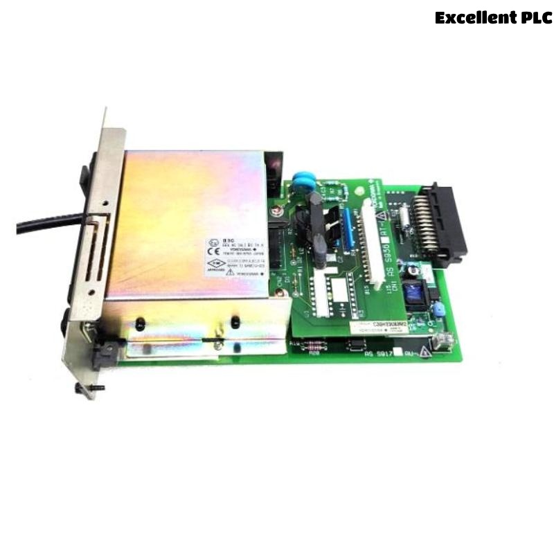
The Yokogawa AIP571 Electrical Transceiver RIO I/O Module is a communication interface module used in Yokogawa CENTUM CS and CENTUM VP Distributed Control Systems (DCS). It establishes high-speed communication links between Remote I/O (RIO) modules and the Field Control Unit (FCU), or between two AIP571 modules, through optical fiber communication. The module provides reliable long-distance data transmission, high immunity to electromagnetic interference, and deterministic communication required for industrial automation applications. Proper installation and commissioning are essential to ensure stable Remote I/O communication and system reliability.
Contents
- 1. Product Overview
- 2. Main Features
- 3. Typical Applications
- 4. Installation Preparation
- 5. Hardware Inspection
- 6. Module Installation
- 7. Optical Fiber Connections
- 8. Communication Configuration
- 9. Commissioning Procedure
- 10. Functional Verification
- 11. Preventive Maintenance
- 12. Practical Installation Case
- 13. Frequently Asked Questions
Product Overview
The AIP571 serves as the electrical transceiver for Yokogawa Remote I/O systems. It converts electrical communication signals to optical signals for transmission over fiber-optic cables, allowing reliable long-distance communication between RIO stations and the FCU while reducing susceptibility to electrical noise. Typical communication speeds are up to 100 Mbps depending on the system configuration.
Main Features
- High-speed optical fiber communication
- Long-distance Remote I/O connectivity
- Electrical-to-optical signal conversion
- Excellent electromagnetic noise immunity
- Industrial-grade communication reliability
- Support for CENTUM CS and CENTUM VP systems
- Modular plug-in design
- Continuous 24-hour industrial operation
Typical Applications
- CENTUM VP Distributed Control Systems
- CENTUM CS automation systems
- Remote I/O stations
- Oil and gas production facilities
- Petrochemical plants
- Power generation facilities
- Large industrial process plants
Installation Preparation
- Review the Remote I/O network architecture.
- Verify AIP571 compatibility with the FCU.
- Prepare ESD protection equipment.
- Inspect optical fiber cables and connectors.
- Schedule installation during an approved maintenance window.
Hardware Inspection
- Verify the module model number.
- Inspect the housing for physical damage.
- Check backplane connectors.
- Inspect fiber-optic ports for contamination.
- Verify LED indicators are intact.
Module Installation
- Place the controller in maintenance mode.
- Wear an anti-static wrist strap.
- Insert the AIP571 into the designated slot.
- Secure the retaining screws.
- Verify complete backplane engagement.
- Inspect module alignment before power-up.
Optical Fiber Connections
- Connect the transmit (TX) fiber to the corresponding receive (RX) port.
- Connect the receive (RX) fiber correctly.
- Clean fiber connectors before installation.
- Observe the minimum fiber bending radius.
- Secure optical connectors to prevent vibration damage.
Communication Configuration
- Assign the correct Remote I/O station address.
- Configure communication parameters.
- Verify optical communication status.
- Register Remote I/O nodes in the engineering database.
- Confirm successful communication initialization.
Commissioning Procedure
VERIFY MODULE INSTALLATION
CONNECT OPTICAL FIBER CABLES
POWER ON THE SYSTEM
VERIFY MODULE DETECTION
CHECK REMOTE I/O COMMUNICATION
VERIFY PROCESS DATA
REVIEW DIAGNOSTIC STATUS
PLACE SYSTEM INTO OPERATION
Functional Verification
- Verify Remote I/O station detection.
- Confirm engineering station communication.
- Verify real-time process data updates.
- Review communication diagnostics.
- Check module status LEDs.
Preventive Maintenance
- Inspect fiber-optic connectors regularly.
- Clean optical ports using approved cleaning tools.
- Verify cable integrity.
- Monitor communication diagnostics.
- Inspect cable routing for mechanical damage.
Practical Installation Case
During the modernization of a refinery control system, an AIP571 module was installed to connect a newly added Remote I/O station located approximately 600 meters from the main control cabinet.
After startup, communication could not be established because the transmit and receive fiber connections had been reversed.
After correcting the fiber connections:
- The Remote I/O station was detected immediately.
- Process signals updated normally.
- Engineering diagnostics reported healthy communication.
- The plant completed commissioning without further communication issues.
Frequently Asked Questions
What is the primary function of the AIP571?
The AIP571 converts electrical communication signals to optical signals and provides high-speed communication between Remote I/O modules and the Field Control Unit over optical fiber.
Why does the AIP571 use optical fiber?
Optical fiber provides long-distance communication, electrical isolation, and strong immunity to electromagnetic interference, making it well suited for industrial automation environments.
What should be verified after installation?
Verify module recognition, Remote I/O communication, fiber connectivity, engineering diagnostics, process data updates, and normal LED status indications.
Summary
Proper installation of the Yokogawa AIP571 Electrical Transceiver RIO I/O Module requires secure module mounting, correct optical fiber connections, accurate communication configuration, comprehensive functional testing, and routine preventive maintenance. Following these procedures ensures reliable long-distance Remote I/O communication and dependable operation of Yokogawa CENTUM CS and CENTUM VP Distributed Control Systems.