 Excellent PLC


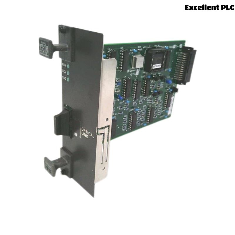
The Yokogawa AIP578 RIO Optical Link Transceiver Board Module is an optical communication interface used in Yokogawa CENTUM CS and CENTUM VP Distributed Control Systems (DCS). It converts RIO bus electrical signals into optical signals and transmits them through a pair of optical fibers, providing reliable long-distance communication between Field Control Units (FCUs), Remote I/O (RIO) node units, and optical bus repeaters. The AIP578 supports V net optical communication over distances of up to 4 km while providing excellent immunity to electromagnetic interference and high communication reliability in industrial environments.
Contents
- 1. Product Overview
- 2. Main Features
- 3. Typical Applications
- 4. Installation Preparation
- 5. Hardware Inspection
- 6. Module Installation
- 7. Optical Fiber Connections
- 8. Communication Configuration
- 9. Commissioning Procedure
- 10. Functional Verification
- 11. Preventive Maintenance
- 12. Practical Installation Case
- 13. Frequently Asked Questions
Product Overview
The AIP578 operates as an optical transceiver for the Yokogawa RIO and V net communication systems. It modulates and demodulates optical signals, transmitting and receiving communication data through dedicated IN and OUT optical connectors. The module includes RDY, RCV, and SND status indicators to assist with installation and diagnostics. Under standard V net applications, the optical communication distance is up to 4 km using multimode fiber.
Main Features
- Optical communication interface for RIO and V net
- Electrical-to-optical signal conversion
- Communication distance up to 4 km
- Excellent immunity to electromagnetic interference
- Dedicated IN and OUT optical connectors
- RDY, RCV and SND diagnostic LEDs
- Industrial modular design
- High reliability for continuous process operation
Typical Applications
- CENTUM VP Distributed Control Systems
- CENTUM CS control systems
- Remote I/O communication networks
- Optical bus repeater systems
- Oil and gas production facilities
- Petrochemical plants
- Power generation facilities
Installation Preparation
- Review the optical network topology.
- Verify module compatibility with the controller.
- Prepare ESD protection equipment.
- Inspect fiber-optic cables and connectors.
- Confirm optical cable routing before installation.
Hardware Inspection
- Verify the AIP578 model number.
- Inspect the module for mechanical damage.
- Check the backplane connector.
- Inspect optical ports for contamination.
- Verify RDY, RCV and SND indicator integrity.
Module Installation
- Place the controller in maintenance mode.
- Wear an approved anti-static wrist strap.
- Insert the AIP578 into the designated communication slot.
- Secure the mounting screws.
- Verify complete engagement with the backplane.
- Inspect module alignment before applying power.
Optical Fiber Connections
- Connect the local OUT port to the remote IN port.
- Connect the local IN port to the remote OUT port.
- Clean all fiber connectors before installation.
- Observe the specified minimum bending radius.
- Secure all optical connectors to prevent vibration.
Communication Configuration
- Configure the Remote I/O communication parameters.
- Verify controller node configuration.
- Confirm optical communication initialization.
- Verify engineering database consistency.
- Check communication status after startup.
Commissioning Procedure
VERIFY MODULE INSTALLATION
CONNECT OPTICAL FIBERS
POWER ON THE CONTROLLER
VERIFY RDY INDICATOR
CHECK RCV AND SND ACTIVITY
VERIFY REMOTE I/O COMMUNICATION
TEST PROCESS DATA
PLACE SYSTEM INTO OPERATION
Functional Verification
- Verify RDY LED remains illuminated.
- Confirm RCV LED flashes during data reception.
- Confirm SND LED flashes during transmission.
- Verify Remote I/O communication.
- Review controller diagnostic messages.
Preventive Maintenance
- Inspect fiber connectors regularly.
- Clean optical connectors using approved cleaning tools.
- Verify cable routing and bend radius.
- Review communication diagnostics.
- Inspect optical connectors for physical damage.
Practical Installation Case
During a DCS modernization project, a new AIP578 module was installed to provide optical communication between the main controller cabinet and a Remote I/O station located approximately 3 km away.
Following startup, the RDY indicator remained off because the receive fiber had been connected to the incorrect port.
After reconnecting the optical fibers correctly:
- The RDY indicator illuminated continuously.
- The RCV and SND indicators showed normal communication activity.
- The Remote I/O station became operational.
- Engineering diagnostics confirmed stable optical communication.
Frequently Asked Questions
What is the function of the AIP578?
The AIP578 converts RIO and V net electrical communication signals into optical signals and provides reliable fiber-optic communication between Yokogawa controllers, Remote I/O stations, and optical repeaters.
What do the RDY, RCV and SND indicators mean?
RDY indicates that a valid optical signal is being received, RCV indicates incoming communication activity, and SND indicates outgoing communication activity. These indicators are also active during self-diagnostic testing.
What is the maximum communication distance?
When used with the supported Yokogawa optical communication system, the AIP578 supports optical transmission distances of up to 4 km using appropriate multimode optical fiber.
Summary
Proper installation of the Yokogawa AIP578 RIO Optical Link Transceiver Board Module requires secure module installation, correct IN/OUT optical fiber connections, clean optical interfaces, accurate communication configuration, and comprehensive commissioning tests. Following these procedures ensures reliable long-distance optical communication and dependable Remote I/O operation in Yokogawa CENTUM CS and CENTUM VP Distributed Control Systems.