 Excellent PLC


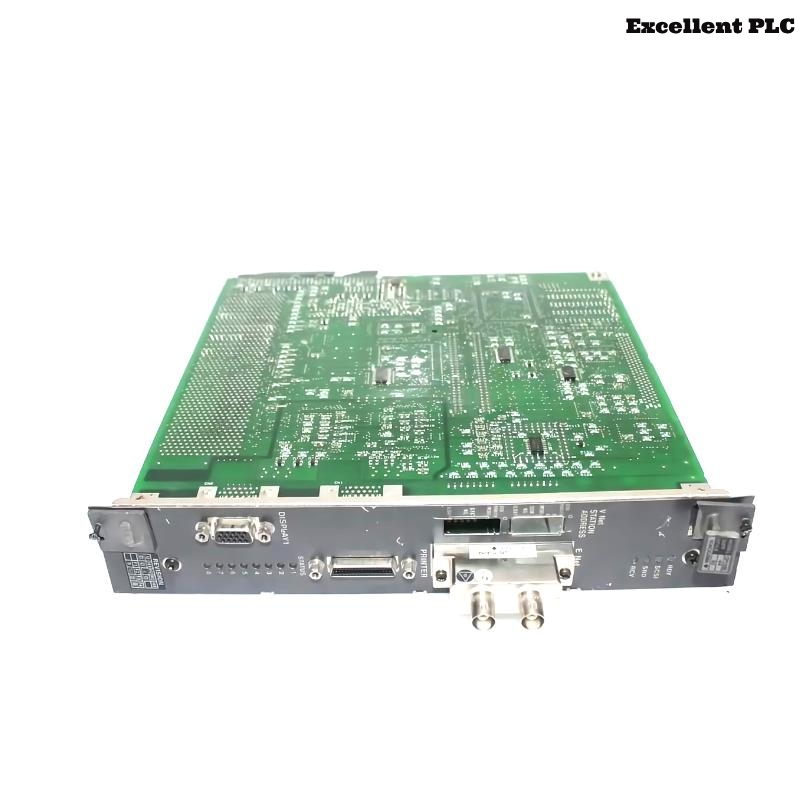
The Yokogawa CP133E-64 CPU Module with Ethernet Interface is the central processor of Yokogawa industrial automation and process control systems. It executes control programs, manages I/O communication, performs system diagnostics, and provides integrated Ethernet connectivity for engineering stations, operator workstations, and industrial networks. Hardware faults, power supply issues, configuration errors, communication failures, or application program problems may prevent normal controller operation. A structured troubleshooting procedure helps identify the root cause quickly and minimizes production downtime.
Contents
- 1. Understanding CPU Module Faults
- 2. Common Failure Symptoms
- 3. Typical Causes
- 4. Initial Hardware Inspection
- 5. Ethernet Communication Verification
- 6. Diagnostic Analysis
- 7. Recommended Troubleshooting Workflow
- 8. Corrective Actions
- 9. Functional Recovery Verification
- 10. Preventive Maintenance
- 11. Industrial Maintenance Case
- 12. Frequently Asked Questions
Understanding CPU Module Faults
The CP133E-64 manages controller execution, communication, and system coordination. Operational problems may result from unstable power supplies, hardware failures, memory corruption, damaged rack connectors, Ethernet network faults, duplicate IP addresses, firmware incompatibility, or application program errors. Before replacing the CPU module, engineers should verify external conditions including power, rack connections, communication cables, and configuration parameters.
Common Failure Symptoms
- CPU does not enter RUN mode.
- RUN or STATUS indicators show fault conditions.
- Engineering workstation cannot connect.
- Ethernet communication is unavailable.
- I/O modules stop updating.
- Controller restarts unexpectedly.
- Diagnostic alarms appear during startup.
- Application program does not execute correctly.
Typical Causes
- Power supply instability.
- Improper CPU installation.
- Damaged rack backplane connector.
- Ethernet cable failure.
- Incorrect IP address configuration.
- Firmware or configuration mismatch.
- Corrupted application program.
- Excessive cabinet temperature.
- Internal CPU hardware failure.
Initial Hardware Inspection
- Verify power supply voltage.
- Inspect CPU status LEDs.
- Confirm the module is fully seated.
- Inspect rack connectors.
- Verify cabinet cooling.
- Review controller diagnostic messages.
Ethernet Communication Verification
- Inspect Ethernet cable integrity.
- Verify switch port status.
- Confirm IP address settings.
- Check subnet and gateway configuration.
- Verify communication with the engineering station.
- Inspect Ethernet connector LEDs.
Diagnostic Analysis
| Observed Condition | Possible Diagnosis |
|---|---|
| CPU does not start | Power supply failure or hardware fault |
| RUN LED remains OFF | Configuration error or corrupted application |
| No Ethernet communication | Incorrect IP settings, cable failure, or switch problem |
| Frequent CPU restart | Power instability, overheating, or hardware failure |
| I/O communication lost | Backplane connection or controller communication fault |
Recommended Troubleshooting Workflow
CHECK SYSTEM DIAGNOSTICS
VERIFY POWER SUPPLY
INSPECT CPU INSTALLATION
CHECK RACK CONNECTIONS
VERIFY ETHERNET SETTINGS
TEST NETWORK COMMUNICATION
DOWNLOAD APPLICATION IF REQUIRED
CONFIRM NORMAL OPERATION
Corrective Actions
- Restore stable power supply.
- Reseat the CPU module.
- Repair damaged rack connectors.
- Replace faulty Ethernet cables.
- Correct network configuration.
- Reload the application program.
- Update firmware if required.
- Replace the CPU module after confirming hardware failure.
Functional Recovery Verification
- Confirm CPU enters RUN mode.
- Verify Ethernet communication.
- Check I/O updates.
- Review diagnostic logs.
- Verify application execution.
- Monitor long-term controller stability.
Preventive Maintenance
- Inspect module status indicators regularly.
- Backup controller programs.
- Verify Ethernet connections.
- Maintain cabinet cooling.
- Review diagnostic history.
- Inspect rack connectors during scheduled shutdowns.
Industrial Maintenance Case
After replacing a network switch during scheduled maintenance at a chemical processing plant, engineers were unable to connect to a CP133E-64 CPU through Ethernet. Inspection confirmed that the CPU was operating normally, but a duplicate IP address had been assigned to another controller during network reconfiguration.
After correcting the IP address conflict, verifying switch configuration, confirming Ethernet connectivity, and testing controller communication:
- The engineering workstation successfully connected to the CPU.
- All I/O communication resumed normally.
- Controller diagnostics reported no active faults.
- Production restarted without replacing the CPU module.
Frequently Asked Questions
Why does the CPU remain in STOP mode?
This may be caused by configuration errors, corrupted application software, hardware faults, startup diagnostics, or unstable power conditions.
Why can’t the engineering workstation communicate through Ethernet?
Common causes include damaged Ethernet cables, switch failures, incorrect IP configuration, duplicate network addresses, firewall restrictions, or communication parameter mismatches.
When should the CP133E-64 CPU module be replaced?
The module should only be replaced after confirming that power supplies, rack connections, Ethernet infrastructure, firmware, configuration, and application software are operating correctly, while the CPU continues to report internal hardware failures or fails to start.
Summary
Effective troubleshooting of the Yokogawa CP133E-64 CPU Module with Ethernet Interface requires systematic verification of power supply stability, hardware installation, rack connections, Ethernet communication, controller configuration, firmware compatibility, and application software. Routine preventive maintenance and regular program backups help ensure reliable long-term operation of Yokogawa industrial control systems.