

Yokogawa SNB10D-215/CU2N installation issues are usually related to ESB Bus configuration mistakes, incorrect node expansion settings, or power redundancy commissioning errors rather than failures of the Safety Node Unit itself. The SNB10D-215/CU2N is a rack-mountable Safety Node Unit designed for dual-redundant ESB Bus architectures and supports safety I/O communication within Yokogawa ProSafe-RS systems. :contentReference[oaicite:0]{index=0}
Contents
- SNB10D-215/CU2N Safety Node Unit Overview
- SNB10D-215/CU2N System Architecture
- Engineering Preparation Before Installation
- Cabinet Design Requirements
- Power Distribution Planning
- Incoming Equipment Verification
- SNB10D-215/CU2N Installation Guide
- ESB Bus Setup Procedure
- Safety I/O Module Integration
- Grounding Strategy
- Initial Power-Up Inspection
- SNB10D-215/CU2N Setup Process
- System Configuration Verification
- Commissioning Workflow
- Safety Function Testing
- Redundancy Validation
- Real Commissioning Experience
- FAQ
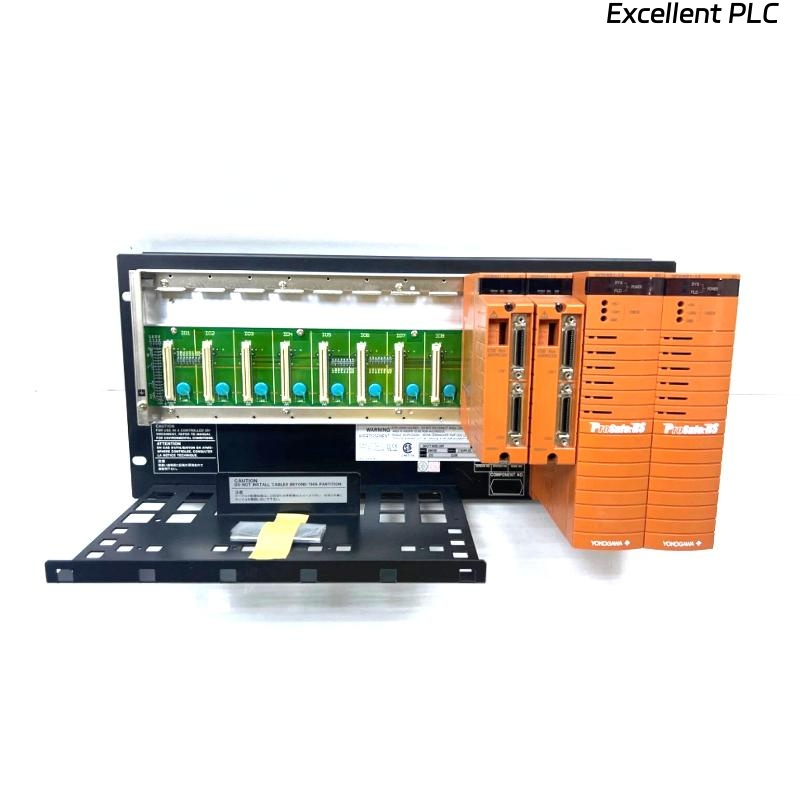
SNB10D-215/CU2N Safety Node Unit Overview
The SNB10D-215/CU2N is a Safety Node Unit for dual-redundant ESB Bus systems. It provides communication between field safety I/O and Safety Control Units while supporting redundant power supplies and node expansion functions. :contentReference[oaicite:1]{index=1}
SNB10D-215/CU2N System Architecture
- Dual-redundant ESB Bus communication
- Distributed safety I/O architecture
- Redundant power supply support
- Remote node deployment
- Safety Instrumented System integration
Engineering Preparation Before Installation
Experienced SIS engineers review architecture drawings before hardware installation.
- Node quantity planning
- I/O capacity analysis
- Safety loop allocation
- ESB Bus routing review
- Expansion strategy validation
Cabinet Design Requirements
The SNB10D series should be installed inside a metallic cabinet to satisfy safety and EMC requirements. :contentReference[oaicite:2]{index=2}
- 19-inch rack support
- Ventilation clearance
- Cable segregation
- Grounding bar installation
- Maintenance accessibility
Power Distribution Planning
The SNB10D-215/CU2N supports dual-redundant power architecture with 100–120 VAC power input. :contentReference[oaicite:3]{index=3}
- Independent feeder design
- Power redundancy verification
- Breaker coordination review
- Voltage stability testing
Incoming Equipment Verification
- Model confirmation
- Connector inspection
- Rack hardware verification
- ESB Bus connector review
- Transit damage inspection
SNB10D-215/CU2N Installation Guide
- Lock out cabinet power.
- Prepare rack position.
- Install the Safety Node Unit.
- Secure mounting hardware.
- Verify alignment.
- Inspect mechanical stability.
ESB Bus Setup Procedure
- Verify cable routing
- Inspect ESB connectors
- Validate communication topology
- Check redundancy paths
- Confirm node addresses
Many startup delays originate from ESB Bus addressing conflicts rather than hardware faults.
Safety I/O Module Integration
- Digital input assignment
- Digital output allocation
- Analog signal grouping
- Shutdown loop mapping
- Voting logic distribution
Grounding Strategy
- Protective earth verification
- Shield continuity testing
- Ground loop prevention
- Cabinet bonding validation
Initial Power-Up Inspection
- LED health review
- Power redundancy confirmation
- Communication diagnostics review
- Alarm monitoring
SNB10D-215/CU2N Setup Process
CHECK POWER STATUS
VERIFY NODE ADDRESS
VALIDATE ESB COMMUNICATION
CONFIRM I/O RECOGNITION
SAVE CONFIGURATION
ARCHIVE BASELINE DATA
System Configuration Verification
- Node identification review
- I/O database validation
- Communication route inspection
- Safety logic verification
- Redundancy parameter review
Commissioning Workflow
Rather than testing every loop immediately, experienced engineers verify infrastructure first.
- Hardware inspection.
- Communication validation.
- Power redundancy testing.
- Signal simulation.
- Integrated safety testing.
Safety Function Testing
- Input simulation testing
- Output verification
- Shutdown response validation
- Alarm functionality checks
- Recovery sequence testing
Redundancy Validation
- Power source failover
- Communication recovery testing
- Node availability checks
- Alarm generation verification
Real Commissioning Experience
During startup of a gas compression station, engineers found that one SNB10D-215/CU2N failed to exchange process data with the Safety Control Unit.
Measured values:
- Supply voltage: 118.9 VAC
- Node status: Healthy
- ESB Bus latency: 148 ms
- I/O status: Intermittent
The maintenance team initially suspected a defective Safety Node Unit.
Further analysis showed that two remote nodes had been assigned the same ESB address during Setup.
After correcting the addressing:
- Latency dropped to 13 ms
- Communication stabilized
- All I/O modules became available
- Commissioning completed successfully
We observed that addressing errors produced symptoms almost identical to hardware failures.
SNB10D-215/CU2N Installation Guide FAQ
What is the primary role of the SNB10D-215/CU2N?
It acts as a Safety Node Unit that transfers safety I/O data through a dual-redundant ESB Bus architecture while supporting redundant power systems. :contentReference[oaicite:4]{index=4}
Does the unit support node expansion?
Yes. The model supports node expansion functions as part of the dual-redundant architecture. :contentReference[oaicite:5]{index=5}
What is the most common commissioning issue?
Field experience shows that addressing and System Configuration errors are more common than hardware failures.
Summary: Successful SNB10D-215/CU2N Setup and Commissioning depend on accurate System Configuration, proper ESB Bus design, redundancy validation, and disciplined safety testing procedures.