

Yokogawa SNB10D-243/CU2N commissioning failures are often caused by ESB Bus communication configuration errors, 24VDC power distribution problems, or incorrect node expansion settings rather than faults within the Safety Node Unit itself. The SNB10D-243/CU2N is a rack-mountable Safety Node Unit designed for ProSafe-RS Safety Instrumented Systems, featuring dual-redundant 24VDC power architecture, ESB Bus communication, and R3 node expansion capability. :contentReference[oaicite:0]{index=0}
Contents
- SNB10D-243/CU2N Safety Node Unit Overview
- SNB10D-243/CU2N Key Features
- Safety System Applications
- Installation Planning
- Environmental Requirements
- 24VDC Power Supply Preparation
- Control Cabinet Requirements
- Pre-Installation Inspection
- SNB10D-243/CU2N Installation Guide
- ESB Bus Setup Strategy
- Safety I/O Module Allocation
- Grounding and EMC Practices
- Startup Verification
- SNB10D-243/CU2N Setup Procedure
- System Configuration Validation
- Commissioning Workflow
- Redundancy Testing
- Real Commissioning Case
- FAQ
SNB10D-243/CU2N Safety Node Unit Overview
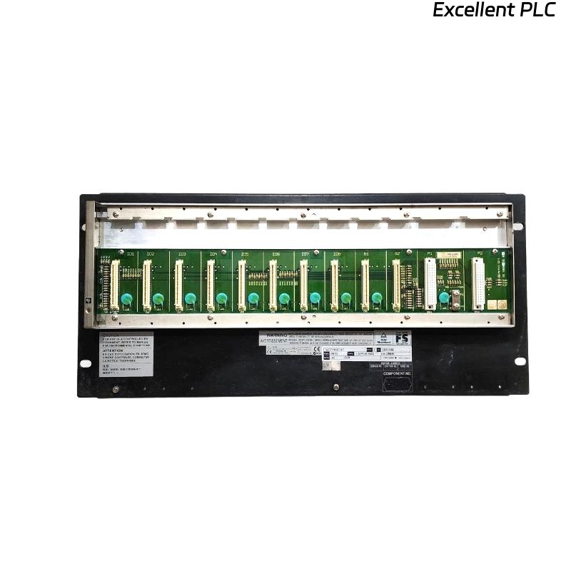
The SNB10D-243/CU2N is a rack-mounted Safety Node Unit that exchanges safety signals with the Safety Control Unit through the ESB Bus while supplying power to installed I/O modules. The model includes dual-redundant 24VDC power architecture and a CU2N ESB Bus connector unit. :contentReference[oaicite:1]{index=1}
SNB10D-243/CU2N Key Features
- Dual-redundant 24VDC power supply
- ESB Bus communication interface
- R3 node expansion license
- ISA G3 conformal coating
- Extended operating temperature design
- Rack-mount installation
Safety System Applications
- Emergency Shutdown Systems
- Fire and Gas Systems
- Burner Management Systems
- Offshore Platforms
- Petrochemical Facilities
- Power Generation Plants
Installation Planning
Experienced SIS engineers verify communication architecture before mounting hardware.
- Determine node quantity
- Review ESB topology
- Allocate I/O capacity
- Define redundancy paths
- Plan maintenance accessibility
Environmental Requirements
- Temperature-controlled cabinet
- Low-vibration environment
- Protected industrial enclosure
- Controlled humidity
- EMC-compliant installation area
24VDC Power Supply Preparation
The SNB10D-243/CU2N uses dual-redundant 24VDC power architecture with approximately 5.5A power requirements. Stable voltage is essential for reliable communication. :contentReference[oaicite:2]{index=2}
- Verify 24VDC stability
- Check redundancy operation
- Inspect protection devices
- Confirm grounding continuity
Control Cabinet Requirements
Yokogawa recommends installation inside a keyed metallic cabinet to maintain safety, EMC, and environmental compliance. :contentReference[oaicite:3]{index=3}
- 19-inch rack support
- Ventilation clearance
- Cable separation
- Ground bar installation
Pre-Installation Inspection
- Verify model number
- Inspect CU2N connector unit
- Check insulating bushings
- Inspect shipping condition
- Review project documentation
SNB10D-243/CU2N Installation Guide
- Isolate all power sources.
- Prepare rack location.
- Install insulating bushings.
- Mount the Safety Node Unit.
- Secure four M5 fixing screws.
- Verify mechanical stability.
ESB Bus Setup Strategy
- Verify CU2N connectivity
- Inspect ESB cable routing
- Check communication redundancy
- Validate node addresses
- Review termination design
Field experience shows that incorrect node addressing causes more startup issues than hardware defects.
Safety I/O Module Allocation
- Digital input grouping
- Digital output assignment
- Analog signal mapping
- Shutdown loop separation
- Voting logic allocation
Grounding and EMC Practices
- Protective earth verification
- Shield continuity inspection
- Ground loop prevention
- Cabinet bonding validation
Startup Verification
- Power LED inspection
- Communication status review
- Node recognition check
- Alarm monitoring
SNB10D-243/CU2N Setup Procedure
APPLY POWER
VERIFY NODE HEALTH
CHECK ESB BUS STATUS
CONFIRM I/O MODULES
VALIDATE COMMUNICATION
SAVE CONFIGURATION
System Configuration Validation
- Node address verification
- I/O mapping review
- Communication parameter validation
- Safety logic inspection
- Redundancy verification
Commissioning Workflow
- Inspect hardware installation.
- Validate communication links.
- Verify power redundancy.
- Simulate field signals.
- Perform integrated testing.
Redundancy Testing
- Power failover verification
- Communication switchover testing
- Node recovery validation
- Alarm generation testing
Real Commissioning Case
During commissioning of a gas processing facility, a newly installed SNB10D-243/CU2N repeatedly generated communication alarms.
- 24VDC measured: 23.1V
- ESB latency: 145 ms
- Node health: Normal
- I/O updates: Intermittent
The maintenance team initially suspected a faulty Safety Node Unit. After detailed investigation, engineers discovered excessive voltage drop caused by undersized power cabling.
After replacing the cable:
- Voltage increased to 24.2V
- Latency dropped to 11 ms
- Communication stabilized
- Commissioning completed successfully
We observed that power quality issues produced symptoms nearly identical to ESB Bus failures.
SNB10D-243/CU2N Installation Guide FAQ
What is the function of the CU2N option?
The CU2N option provides the ESB Bus connector interface used for communication with the Safety Control Unit. :contentReference[oaicite:4]{index=4}
What power supply is used by the SNB10D-243/CU2N?
The -243 suffix indicates a dual-redundant 24VDC power configuration. :contentReference[oaicite:5]{index=5}
Why should System Configuration be validated before commissioning?
Address conflicts and mapping errors frequently generate startup communication alarms even when hardware is functioning correctly.
Summary: Successful SNB10D-243/CU2N Setup and Commissioning depend on proper ESB Bus design, stable 24VDC power, accurate System Configuration, and complete redundancy verification.