

Yokogawa SNB10D-223/CU2N installation problems are most often related to ESB Bus configuration errors, node addressing conflicts, or redundant power commissioning issues rather than actual Safety Node Unit hardware defects. Proper Setup, System Configuration, and Commissioning procedures are essential because the SNB10D-223/CU2N serves as the communication bridge between distributed safety I/O modules and the central ProSafe-RS Safety Control Unit. The unit supports dual-redundant power architecture and ESB Bus communication for high-availability Safety Instrumented Systems (SIS). :contentReference[oaicite:0]{index=0}
Contents
- SNB10D-223/CU2N Safety Node Unit Overview
- SNB10D-223/CU2N Application Architecture
- Engineering Design Considerations
- Installation Environment Requirements
- Power System Preparation
- Equipment Inspection Before Installation
- Rack Mounting Requirements
- SNB10D-223/CU2N Installation Guide
- ESB Bus Integration Strategy
- Safety I/O Module Arrangement
- Grounding and Shielding Practices
- Initial Startup Verification
- SNB10D-223/CU2N Setup Procedure
- System Configuration Validation
- Commissioning Methodology
- Functional Testing
- Redundancy Verification
- Real Commissioning Case
- FAQ
SNB10D-223/CU2N Safety Node Unit Overview
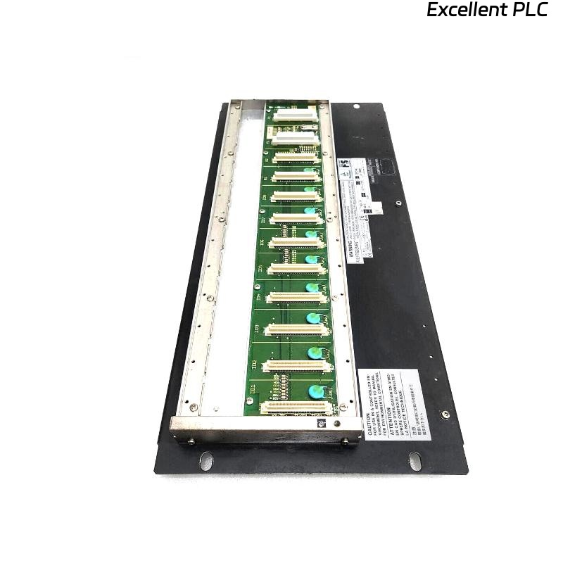
The SNB10D-223/CU2N is a rack-mounted Safety Node Unit used within Yokogawa ProSafe-RS systems. It transmits analog and digital safety signals through the ESB Bus and supplies power to installed safety I/O modules. Up to multiple safety nodes can be integrated into a distributed safety architecture. :contentReference[oaicite:1]{index=1}
SNB10D-223/CU2N Application Architecture
- Emergency Shutdown Systems (ESD)
- Fire and Gas Systems (F&G)
- Refinery SIS applications
- Petrochemical safety platforms
- LNG process safety systems
Engineering Design Considerations
Before installation begins, engineers should verify:
- Node quantity calculations
- Communication topology
- I/O loading requirements
- Safety loop allocation
- Redundancy philosophy
- Future expansion capacity
Installation Environment Requirements
- Temperature-controlled cabinet
- Low vibration location
- EMC-compliant installation area
- Dry and dust-controlled environment
- Sufficient service clearance
Power System Preparation
The SNB10D-223/CU2N supports dual-redundant power architecture and is available in versions supporting 100–120 VAC, 220–240 VAC, or 24 VDC power options depending on configuration. :contentReference[oaicite:2]{index=2}
- Verify supply voltage
- Inspect circuit protection
- Confirm redundancy availability
- Validate grounding integrity
Equipment Inspection Before Installation
- Confirm model number
- Inspect ESB connectors
- Verify rack accessories
- Check shipping condition
- Review installation drawings
Rack Mounting Requirements
The Safety Node Unit is designed for rack mounting using four fixing points. Mechanical stability directly affects long-term reliability. :contentReference[oaicite:3]{index=3}
SNB10D-223/CU2N Installation Guide
- Isolate cabinet power.
- Prepare rack mounting location.
- Install the Safety Node Unit.
- Secure mounting hardware.
- Verify alignment.
- Inspect mechanical stability.
ESB Bus Integration Strategy
- Validate node addressing
- Inspect communication cables
- Verify bus redundancy
- Confirm network topology
- Review termination strategy
Most communication startup issues originate from addressing conflicts or incorrect ESB routing.
Safety I/O Module Arrangement
- Digital input allocation
- Digital output grouping
- Analog channel planning
- Shutdown loop assignment
- Voting architecture distribution
Grounding and Shielding Practices
- Protective earth verification
- Shield continuity testing
- Cabinet bonding validation
- Ground loop elimination
Initial Startup Verification
- Power module health review
- ESB communication verification
- Node recognition inspection
- Alarm monitoring
SNB10D-223/CU2N Setup Procedure
POWER ON SYSTEM
VERIFY NODE STATUS
CHECK COMMUNICATION LINKS
VALIDATE I/O RECOGNITION
SAVE CONFIGURATION
ARCHIVE BASELINE DATA
System Configuration Validation
- Node address review
- I/O mapping verification
- Communication path validation
- Safety logic review
- Redundancy parameter inspection
Commissioning Methodology
Experienced engineers commission infrastructure first and safety functions second.
- Verify hardware.
- Validate communication.
- Test redundancy.
- Simulate field signals.
- Perform integrated safety testing.
Functional Testing
- Digital input simulation
- Output response testing
- Alarm validation
- Shutdown logic verification
- Recovery sequence testing
Redundancy Verification
- Power failover testing
- Communication switchover testing
- Node recovery validation
- Alarm generation checks
Real Commissioning Case
During a refinery SIS expansion project, engineers observed that a newly installed SNB10D-223/CU2N failed to exchange data with the Safety Control Unit.
Measured values:
- Supply voltage: 118.8 VAC
- Communication latency: 165 ms
- Node health: Normal
- I/O visibility: Partial
The maintenance team initially suspected an ESB interface failure.
Further investigation showed that two Safety Node Units had identical node addresses in the System Configuration database.
After correcting the addressing:
- Latency decreased to 11 ms
- All I/O modules became visible
- Communication alarms disappeared
- Commissioning completed successfully
We observed that a configuration error produced symptoms nearly identical to hardware failure.
SNB10D-223/CU2N Installation Guide FAQ
What is the primary function of the SNB10D-223/CU2N?
It serves as a Safety Node Unit that transfers field safety signals to the Safety Control Unit through the ESB Bus while supplying power to installed I/O modules. :contentReference[oaicite:4]{index=4}
Does the SNB10D-223/CU2N support redundant power supplies?
Yes. The model supports dual-redundant power architecture for high-availability safety systems. :contentReference[oaicite:5]{index=5}
What is the most common commissioning issue?
Node addressing and System Configuration errors are encountered more frequently than hardware failures.
Summary: Successful SNB10D-223/CU2N Setup and Commissioning depend on correct ESB Bus design, accurate System Configuration, proper redundancy testing, and disciplined safety verification procedures.