

Yokogawa SPW481-53 power supply module installation problems are usually caused by grounding defects, overloaded power distribution networks, or incorrect AC input verification rather than failures of the power module itself. In CENTUM VP and ProSafe-RS projects, unstable power architecture can trigger controller faults, communication alarms, and unexpected system shutdowns long before a power supply alarm appears.
Contents
- SPW481-53 Power Supply Module Overview
- SPW481-53 Application in DCS and SIS Systems
- SPW481-53 Power Module Specifications
- Installation Planning Strategy
- Control Cabinet Preparation
- SPW481-53 Grounding Requirements
- Input Power Wiring Guide
- Load Analysis Before Startup
- SPW481-53 Module Installation
- Power Supply Module Setup
- System Configuration Verification
- Commissioning Procedure
- Power System Validation
- Real Commissioning Case
- FAQ
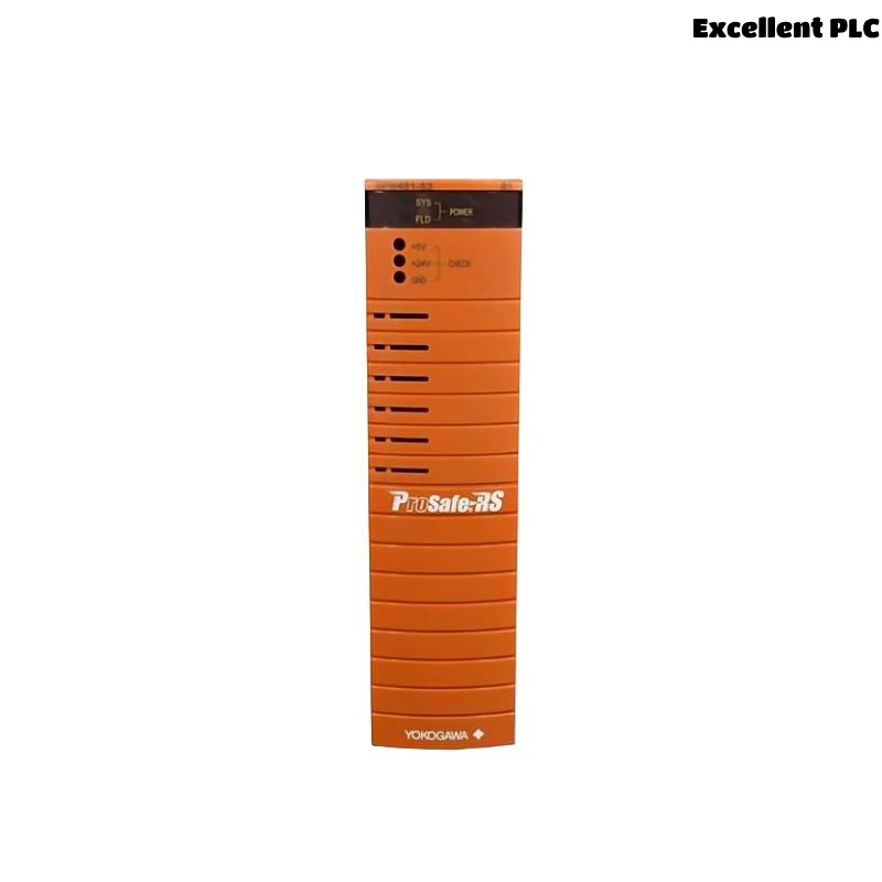
Yokogawa SPW481-53 Power Supply Module Overview
The Yokogawa SPW481-53 is a Power Supply Module designed for industrial automation systems. The SPW481 series accepts 100–120 VAC input power and provides regulated power distribution for control system components. The module supports industrial ISA G3 environmental requirements and can be applied in redundant system architectures. :contentReference[oaicite:0]{index=0}
SPW481-53 Application in DCS and SIS Systems
The SPW481-53 is commonly installed in:
- CENTUM VP systems
- ProSafe-RS safety systems
- Field Control Stations
- Safety Control Stations
- Remote I/O cabinets
- Critical process control applications
SPW481-53 Power Module Specifications
- 100–120 VAC input power
- Industrial power supply architecture
- ISA G3 environmental rating
- Industrial temperature operation
- Support for redundant installations
Reference data indicates operation within ISA G3 environments and industrial temperature ranges suitable for process plants. :contentReference[oaicite:1]{index=1}
SPW481-53 Installation Planning Strategy
Experienced commissioning engineers evaluate the complete power distribution network before installing the module.
- Incoming utility verification
- UPS architecture review
- Grounding assessment
- Cabinet cooling review
- Load calculations
- Redundancy planning
Control Cabinet Preparation for SPW481-53 Installation
The control cabinet should provide:
- Adequate airflow
- Dust protection
- Stable temperature
- Accessible maintenance space
- Separate routing for power and signal cables
Poor cabinet design often causes thermal stress that affects multiple modules simultaneously.
SPW481-53 Grounding Requirements
Grounding quality directly affects power system stability.
- Verify protective earth continuity
- Inspect grounding conductors
- Eliminate ground loops
- Confirm cabinet bonding integrity
Many communication alarms observed during startup are ultimately traced to grounding deficiencies.
SPW481-53 Input Power Wiring Guide
- Isolate incoming power.
- Verify voltage rating.
- Connect Line terminal.
- Connect Neutral terminal.
- Connect protective earth.
- Inspect terminal torque.
The SPW481 family is designed for 100–120 VAC input applications. :contentReference[oaicite:2]{index=2}
Load Analysis Before Startup
Before energization, engineers should calculate total connected load.
- Controller consumption
- I/O module consumption
- Communication module consumption
- Future expansion capacity
Target loading should remain below maximum design limits to improve long-term reliability.
SPW481-53 Module Installation
After completing wiring inspections:
- Insert the module.
- Inspect connector engagement.
- Secure mounting hardware.
- Verify airflow clearance.
- Document serial information.
SPW481-53 Power Supply Module Setup
During initial startup, record baseline operating values.
CHECK INPUT VOLTAGE
VERIFY OUTPUT STATUS
CHECK LED INDICATORS
VERIFY EARTH CONTINUITY
RECORD BASELINE VALUES
Status indicators should be verified before connecting critical controllers. Available technical references describe dedicated status indicators for system and field power outputs. :contentReference[oaicite:3]{index=3}
System Configuration Verification
System Configuration records should include:
- Power source details
- Circuit identification
- Load allocation
- Redundancy assignments
- Maintenance baseline values
SPW481-53 Commissioning Procedure
- No-load startup verification
- Partial load verification
- Full load verification
- Power recovery testing
- Alarm testing
- Redundancy validation
Commissioning should always verify system behavior under both normal and abnormal operating conditions.
SPW481-53 Power System Validation
Validation activities should confirm:
- Stable output voltage
- Acceptable temperature rise
- Reliable startup performance
- No abnormal alarms
- Successful recovery after power interruption
Real SPW481-53 Commissioning Case
During startup of a fertilizer production unit, engineers reported intermittent communication faults affecting several field controllers.
Measurements showed:
- Input voltage: 117 VAC
- Cabinet temperature: 54°C
- Load utilization: 89%
- Ground resistance: 14.7 Ω
The project team initially suspected network hardware issues.
However, thermal inspection identified restricted airflow near the SPW481-53 Power Supply Module.
After rearranging cable routing and improving ventilation:
- Cabinet temperature dropped to 37°C
- Communication alarms disappeared
- Controller stability improved significantly
We observed that power-system thermal stress was affecting multiple subsystems simultaneously.
SPW481-53 Installation Guide FAQ
What input voltage does the Yokogawa SPW481-53 use?
The SPW481-53 is designed for 100–120 VAC input power applications. :contentReference[oaicite:4]{index=4}
Can the SPW481-53 support redundant system architectures?
Yes. Technical references indicate support for redundant power system configurations in industrial control applications. :contentReference[oaicite:5]{index=5}
What should be checked first during commissioning?
Input voltage, grounding integrity, cabinet temperature, and load distribution should be verified before connecting critical automation equipment.
Summary: Successful Yokogawa SPW481-53 Installation Guide execution depends on proper power planning, grounding quality, load management, thermal control, System Configuration validation, and comprehensive commissioning testing.