

Yokogawa SSC10S-F Safety Control Unit installation projects are most successful when engineers focus on cabinet architecture, safety network integrity, and system configuration before downloading application logic. In practical SIS commissioning, configuration mismatches create more startup delays than hardware defects.
Contents
- Yokogawa SSC10S-F Safety Control Unit Overview
- SSC10S-F Installation Planning Strategy
- Safety Control Unit Mounting Requirements
- SSC10S-F Setup and System Configuration
- Commissioning Validation Procedure
- Field Commissioning Case
- FAQ
Yokogawa SSC10S-F Safety Control Unit Overview
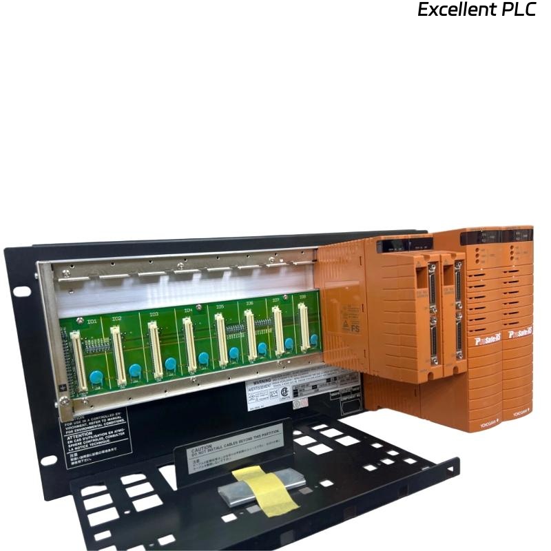
The Yokogawa SSC10S-F Safety Control Unit serves as a core controller within Safety Instrumented Systems (SIS). It executes safety logic, processes critical field signals, and manages shutdown actions when hazardous process conditions occur. The unit is commonly deployed in refinery, petrochemical, LNG, and power generation applications where high reliability is required.
Unlike standard PLC Controllers, safety controllers require strict installation practices to maintain safety integrity and system availability.
SSC10S-F Installation Planning Strategy
Before installation begins, engineering teams should verify the complete system architecture.
- Safety Requirement Specification approved
- Controller cabinet fully grounded
- Power distribution verified
- Network topology documented
- I/O allocation completed
- Cause-and-effect matrix reviewed
From field experience, incomplete I/O mapping is one of the most common causes of commissioning rework.
SSC10S-F Safety Control Unit Mounting Requirements
Proper installation begins with mechanical and electrical preparation.
Cabinet Environment
- Stable ambient temperature
- Controlled humidity
- Adequate ventilation
- Low vibration environment
Grounding Practices
Safety systems are highly sensitive to grounding quality. Ground resistance should remain within project specifications.
Poor grounding can introduce communication instability and false diagnostic alarms.
Cable Separation
- Separate signal cables from power cables
- Use shielded communication wiring
- Avoid parallel routing near VFD output cables
- Maintain proper cable identification
SSC10S-F Setup and System Configuration
After installation, engineers should complete the setup sequence systematically.
- Apply controller power.
- Verify CPU diagnostics.
- Check communication status.
- Import project database.
- Download application logic.
- Verify I/O assignment.
- Confirm safety interlock status.
System Configuration should always be backed up before logic deployment.
VERIFY CPU STATUS
CHECK NETWORK LINK
VERIFY I/O HEALTH
DOWNLOAD LOGIC
SAVE CONFIGURATION
GENERATE BACKUP
SSC10S-F Commissioning Validation Procedure
Commissioning should focus on proving that safety functions operate correctly under both normal and abnormal conditions.
- Input simulation testing
- Shutdown logic verification
- Output response validation
- Communication integrity checks
- Alarm management verification
- Power recovery testing
Many projects complete software testing but overlook field loop validation. This often leads to startup delays during final plant acceptance.
Real Commissioning Experience with SSC10S-F
During commissioning of a gas compression station, engineers observed intermittent communication alarms after controller startup.
Initial findings showed:
- Power supply stable at 24.1 VDC
- CPU diagnostics normal
- Network response time fluctuating between 15 ms and 240 ms
Rather than replacing the Safety Control Unit, the engineering team reviewed cable routing.
Investigation revealed communication cables installed adjacent to high-power motor feeders.
After rerouting the cables and improving shield termination:
- Network latency reduced below 20 ms
- Communication alarms disappeared
- System commissioning completed successfully
This installation guide example demonstrates that environmental factors frequently create symptoms that resemble controller faults.
SSC10S-F Installation Guide FAQ
Can the SSC10S-F Safety Control Unit be installed in a standard PLC cabinet?
It can be installed in a shared cabinet only if safety segregation, grounding, and environmental requirements are satisfied.
What should be checked before downloading the safety application?
Verify communication health, I/O mapping, controller diagnostics, and project configuration consistency.
Why is field loop testing important during commissioning?
Field loop testing confirms that sensors, logic, and final control elements operate together as required by the safety design.
Summary: Successful SSC10S-F Installation Guide execution requires careful planning, proper grounding, reliable communication infrastructure, accurate system configuration, and comprehensive commissioning validation.