

Yokogawa SSC10D-S2111 installation projects typically encounter more issues during network configuration and redundancy verification than during hardware mounting. For ProSafe-RS systems, successful commissioning depends on validating the duplex architecture before safety logic is placed into service. The SSC10D-S2111 is designed as a duplexed Safety Control Unit for Safety Instrumented System (SIS) applications and supports redundant processor and communication architectures. :contentReference[oaicite:0]{index=0}
Contents
- SSC10D-S2111 Safety Control Unit Overview
- Engineering Preparation Before Installation
- SSC10D-S2111 Hardware Installation Guide
- Safety Network and System Configuration
- SSC10D-S2111 Commissioning Strategy
- Safety Function Validation
- Real Startup Experience
- FAQ
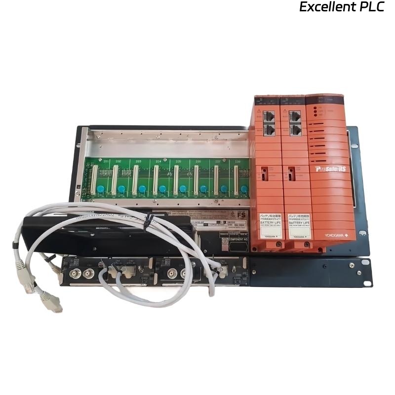
Yokogawa SSC10D-S2111 Safety Control Unit Overview
The SSC10D-S2111 Safety Control Unit is commonly deployed in emergency shutdown systems, fire and gas systems, burner management systems, and other SIL-rated applications. The controller operates within the ProSafe-RS platform and supports redundant communication and processor architectures to improve system availability. :contentReference[oaicite:1]{index=1}
Engineering Preparation Before SSC10D-S2111 Installation
Experienced SIS engineers usually verify the following items before rack installation:
- Approved Safety Requirement Specification (SRS)
- Completed Cause & Effect Matrix
- Validated I/O List
- Power distribution drawings
- Network architecture drawings
- Grounding verification report
Many commissioning delays originate from undocumented modifications made during construction rather than controller configuration errors.
SSC10D-S2111 Hardware Installation Guide
Rack Installation Requirements
The Safety Control Unit should be installed inside a dedicated control cabinet with adequate cooling and maintenance access.
- Verify rack alignment before tightening hardware.
- Confirm vibration-free mounting surfaces.
- Inspect module connectors for transport damage.
- Document serial numbers before energization.
Power Supply Verification
Before applying power:
- Measure incoming voltage.
- Verify protective earth continuity.
- Check redundant power feeds.
- Inspect terminal torque values.
Field experience shows loose power terminals can generate intermittent diagnostics that resemble processor faults.
SSC10D-S2111 Safety Network and System Configuration
System Configuration should be completed before logic download.
- Assign controller node addresses.
- Verify Vnet/IP communication.
- Check network redundancy status.
- Confirm engineering workstation access.
- Validate time synchronization.
VERIFY CPU STATUS
CHECK NETWORK LINK
CHECK REDUNDANCY
VERIFY NODE ADDRESS
DOWNLOAD DATABASE
SAVE BACKUP
The ProSafe-RS architecture allows integration between SIS and DCS environments while maintaining safety functionality. :contentReference[oaicite:2]{index=2}
SSC10D-S2111 Commissioning Strategy
Rather than downloading logic immediately, experienced engineers verify controller health first.
- Processor synchronization check
- Communication redundancy test
- I/O channel diagnostics
- Alarm management review
- Application download verification
A phased commissioning strategy reduces troubleshooting time during plant startup.
SSC10D-S2111 Safety Function Validation
Every Safety Control Unit should undergo functional testing before handover.
- Input simulation tests
- Emergency shutdown testing
- Output trip verification
- Failover testing
- Power interruption testing
- Communication path validation
Failover testing is particularly important because the SSC10D-S2111 utilizes a duplex architecture designed to maintain operation during component failures. :contentReference[oaicite:3]{index=3}
Real Commissioning Case with SSC10D-S2111
During startup of a petrochemical compressor train, engineers observed recurring communication diagnostics after database download.
Measured values were:
- Controller CPU load: 38%
- Power supply voltage: 24.2 VDC
- Network latency: 185 ms peak
- Ground resistance: 16.8 Ω
Initial suspicion focused on the Safety Control Unit hardware.
However, investigation revealed multiple shield terminations bonded at different cabinet locations, creating ground loop currents.
After correcting the grounding arrangement:
- Network latency decreased below 20 ms
- Communication diagnostics disappeared
- Commissioning completed without module replacement
This case highlights why installation quality should always be verified before replacing SIS hardware.
SSC10D-S2111 Installation Guide FAQ
Can the SSC10D-S2111 be commissioned without redundancy testing?
Redundancy testing is strongly recommended because it validates the duplex architecture during abnormal operating conditions.
What causes most startup issues in SSC10D-S2111 projects?
Grounding errors, communication configuration problems, and incorrect system configuration are more common than hardware failures.
Why should engineers create a configuration backup before commissioning?
A verified backup simplifies recovery if logic modifications or configuration mismatches occur during startup activities.
Summary: Successful SSC10D-S2111 Installation Guide implementation requires disciplined preparation, proper grounding, redundant network verification, structured commissioning, and comprehensive safety validation before operational release.