

Table of Contents
- 21500-00-08-10-02 Installation Overview
- 7200 5 mm Probe Function in Monitoring Systems
- Probe Installation Preparation and Inspection
- 7200 Probe Mechanical Mounting Method
- Probe Gap Adjustment and Voltage Calibration
- Extension Cable and Monitoring Module Setup
- Commissioning and Dynamic Signal Validation
- Real Field Installation Case
- Installation FAQ
- Final Engineering Summary
21500-00-08-10-02 Installation Overview
Bently Nevada 21500-00-08-10-02 7200 5 mm probe installation accuracy directly affects shaft vibration and position monitoring reliability. Incorrect probe gap or mounting angle often causes unstable signal output during startup and load changes.
This Installation Guide explains practical field Setup methods for probe mounting, signal calibration, and vibration monitoring Commissioning.
7200 5 mm Probe Function in Monitoring Systems
- Measures shaft vibration and displacement using eddy current technology
- Provides continuous signal feedback to monitoring modules
- Supports rotating equipment protection systems
- Interfaces with PLC Controller and vibration monitoring racks
Probe Installation Preparation and Inspection
- Inspect probe tip for physical damage
- Verify shaft target material compatibility
- Check mounting bracket rigidity
- Ensure correct extension cable type and length
7200 Probe Mechanical Mounting Method
- Install probe perpendicular to rotating surface
- Avoid excessive thread force during installation
- Maintain sufficient clearance around probe body
- Secure mounting to prevent vibration loosening
  // Probe Mounting Verification
  IF Probe_Angle != 90deg THEN
      Signal_Linear = FALSE;
  ELSE
      Continue_Commissioning();
  END_IF;
Probe Gap Adjustment and Voltage Calibration
- Adjust probe until output voltage reaches operating range
- Typical static gap voltage: -8V to -10V
- Monitor voltage stability during shaft rotation
- Record baseline gap values for future Troubleshooting
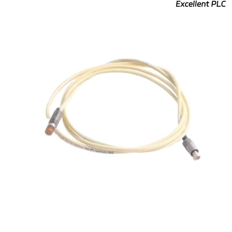
Extension Cable and Monitoring Module Setup
- Use matched extension cable for 7200 probe system
- Keep signal cables away from motor power wiring
- Ensure proper grounding and shielding
- Verify System Configuration in monitoring rack
Commissioning and Dynamic Signal Validation
- Observe waveform during machine startup
- Check vibration trends across speed changes
- Verify stable gap voltage under operating load
- Confirm alarm thresholds function correctly
Real Field Installation Case
During commissioning of an industrial blower, shaft displacement readings became unstable after startup:
- Gap voltage shifted from -9V to -6.2V
- Vibration trend fluctuated abnormally
We observed that the probe bracket lacked rigidity and vibrated with the machine casing.
After corrective action:
- Reinforced mounting structure
- Recalibrated probe gap to -9.1V
Result:
- Stable vibration waveform restored
- Monitoring accuracy improved significantly
Installation FAQ
What gap voltage should be used for the 7200 5 mm probe?
The normal operating range is typically between -8V and -10V DC.
Why is mounting rigidity important?
A flexible mounting structure can introduce false vibration signals.
Can cable routing affect probe measurements?
Yes. Poor shielding or proximity to power cables can introduce EMI interference.
Final Engineering Summary
The Bently Nevada 21500-00-08-10-02 Installation Guide demonstrates that proper probe alignment, rigid mounting, and accurate gap Setup are critical for reliable vibration monitoring and long-term machine protection.