

Table of Contents
- 21747-045-01 Installation Overview
- Proximitor Extension Cable Function in Monitoring Systems
- Site Evaluation Before Cable Installation
- Shielded Cable Routing and Mechanical Protection
- Connector Assembly and Shielding Continuity
- Electrical Validation and System Configuration
- Commissioning and Dynamic Signal Verification
- Real Turbine Installation Experience
- Installation FAQ
- Final Engineering Summary
21747-045-01 Installation Overview
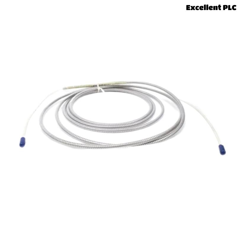
Bently Nevada 21747-045-01 proximitor probe extension cable installation directly affects shaft vibration signal integrity and machinery protection reliability. In high-speed rotating equipment, poor shielding continuity and incorrect cable routing frequently create unstable displacement readings and intermittent monitoring alarms.
This Installation Guide explains practical Setup methods for extension cable routing, connector assembly, shielding protection, and vibration monitoring Commissioning.
Proximitor Extension Cable Function in Monitoring Systems
- Transfers shaft vibration and displacement signals
- Connects proximity probes to proximitor sensors
- Supports long-distance signal transmission
- Interfaces with PLC Controller and machinery monitoring modules
Site Evaluation Before Cable Installation
- Inspect cable tray conditions before routing
- Verify separation from high-current power systems
- Check connector condition before assembly
- Confirm grounding points across the monitoring network
Shielded Cable Routing and Mechanical Protection
- Route extension cable away from inverter wiring
- Use grounded metallic trays whenever possible
- Avoid sharp cable bending near connectors
- Secure cable to reduce vibration-induced movement
  // Cable Shielding Verification
  IF Shield_Continuity = FALSE THEN
      Signal_Noise_Risk = HIGH;
  ELSE
      Monitoring_Stability = NORMAL;
  END_IF;
Connector Assembly and Shielding Continuity
- Clean connector surfaces before coupling
- Apply proper tightening torque to connectors
- Protect connectors from oil contamination
- Verify shielding continuity after installation
Electrical Validation and System Configuration
- Verify cable impedance compatibility
- Check monitoring rack scaling parameters
- Confirm alarm threshold configuration
- Inspect grounding continuity across all monitoring channels
Commissioning and Dynamic Signal Verification
- Observe waveform quality during startup
- Monitor displacement stability at rated speed
- Check signal noise under load changes
- Verify long-term monitoring consistency
Real Turbine Installation Experience
During commissioning of a steam turbine vibration monitoring system, intermittent shaft displacement alarms occurred during startup:
- Signal spikes exceeded baseline by 36%
- Waveform distortion increased near operating speed
We observed that the extension cable shielding continuity was interrupted near a field junction box.
After corrective actions:
- Repaired shielding continuity
- Improved cable separation from motor power wiring
Result:
- Stable shaft monitoring restored
- False vibration alarms eliminated
Installation FAQ
Why is shielding continuity important for extension cables?
Shielding continuity protects vibration signals from EMI interference and electrical noise.
Can cable routing affect vibration monitoring accuracy?
Yes. Routing extension cables near inverter systems may introduce signal distortion.
Should extension cables be secured mechanically?
Yes. Unsupported cable movement can create connector stress and unstable signal conditions.
Final Engineering Summary
The Bently Nevada 21747-045-01 Installation Guide demonstrates that stable cable routing, proper shielding continuity, and accurate System Configuration are essential for reliable vibration monitoring performance.