

Table of Contents
- EB401 Installation Overview
- Bus Interface Module Function
- EB401 Functional Features
- Pre-Installation Inspection Procedure
- Module Installation and Rack Mounting
- Communication Wiring and Grounding Requirements
- Bus Communication Configuration and Setup
- Industrial Automation System Commissioning
- Communication Stability Optimization Methods
- Real Industrial Communication Application
- Installation FAQ
- Final Engineering Summary
EB401 Installation Overview
YOKOGAWA EB401 bus interface module installation quality directly affects industrial automation communication stability and distributed control system reliability. Incorrect communication wiring, unstable grounding continuity, and improper module installation frequently create controller communication failures, unstable data exchange, and unexpected automation system interruptions.
This Installation Guide explains practical Setup methods for communication integration, module installation, wiring inspection, grounding verification, and industrial automation Commissioning.
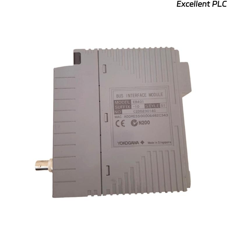
Bus Interface Module Function
- Provides industrial bus communication interface capability
- Supports distributed control system data exchange
- Integrates communication between controllers and I/O systems
- Improves industrial automation communication reliability
EB401 Functional Features
- High-speed industrial communication architecture
- Reliable bus data transmission capability
- Industrial-grade communication stability design
- Compact modular rack installation structure
- Suitable for harsh industrial automation environments
The YOKOGAWA EB401 bus interface module is designed for distributed industrial automation systems requiring stable communication performance and continuous operational reliability.
Pre-Installation Inspection Procedure
- Inspect module housing and communication connectors
- Verify communication cable integrity
- Check grounding continuity within the control cabinet
- Inspect cabinet cooling airflow and environmental conditions
Module Installation and Rack Mounting
Proper interface module installation is essential for stable communication operation and long-term industrial automation reliability.
- Insert the module securely into the designated rack slot
- Verify connector engagement and locking stability
- Maintain adequate airflow around communication modules
- Inspect backplane communication connections before startup
  // Communication Startup Verification
  IF Bus_Communication_Ready = TRUE THEN
      Initialize_Interface_Module();
      Verify_Data_Transmission();
  ELSE
      Inspect_Communication_System();
  END_IF;
Communication Wiring and Grounding Requirements
- Use industrial-grade communication cables
- Maintain stable grounding continuity throughout the cabinet
- Separate communication wiring from high-voltage power cables
- Verify connector and terminal tightness before energizing
Bus Communication Configuration and Setup
- Verify communication network parameters
- Check controller communication address assignments
- Inspect communication diagnostics and status indicators
- Validate stable data exchange between connected systems
Industrial Automation System Commissioning
- Observe communication stability during startup procedures
- Verify communication integrity and response time
- Check diagnostic alarms and communication status
- Validate controller and I/O communication performance
Communication Stability Optimization Methods
- Improve cabinet grounding continuity
- Reduce EMI exposure near communication cables
- Maintain proper cabinet cooling airflow
- Record baseline communication performance data
Real Industrial Communication Application
During startup of a refinery distributed control system, intermittent communication instability appeared between process controllers and remote I/O stations:
- Communication alarms appeared intermittently
- Remote data updates became unstable during high-load operation
Investigation revealed unstable grounding continuity and improper communication cable routing near high-voltage wiring.
After corrective actions:
- Improved grounding continuity connections
- Separated communication and power cable routing
Result:
- Stable bus communication restored
- Industrial automation reliability improved significantly
Installation FAQ
Why is grounding continuity important for bus communication modules?
Proper grounding continuity reduces EMI interference and improves communication reliability.
Can communication cables be routed beside power wiring?
No. Communication wiring should be separated from high-voltage power cables to reduce electrical noise interference.
Can inadequate cooling affect communication stability?
Yes. Excessive temperature conditions may create communication instability and hardware performance degradation.
Final Engineering Summary
The YOKOGAWA EB401 Installation Guide demonstrates that reliable industrial automation communication depends on stable bus network configuration, proper grounding continuity, optimized cable routing, and disciplined system Commissioning.