

Table of Contents
- AMM42 Installation Overview
- Multiplexer Input Module Function
- AMM42 Functional Features
- Pre-Installation Inspection Procedure
- Module Installation and Rack Mounting
- 2-Wire Transmitter Wiring Requirements
- Signal Configuration and DCS Integration
- Industrial Automation Commissioning
- Signal Stability Optimization Methods
- Industrial Application Example
- Installation FAQ
- Engineering Summary
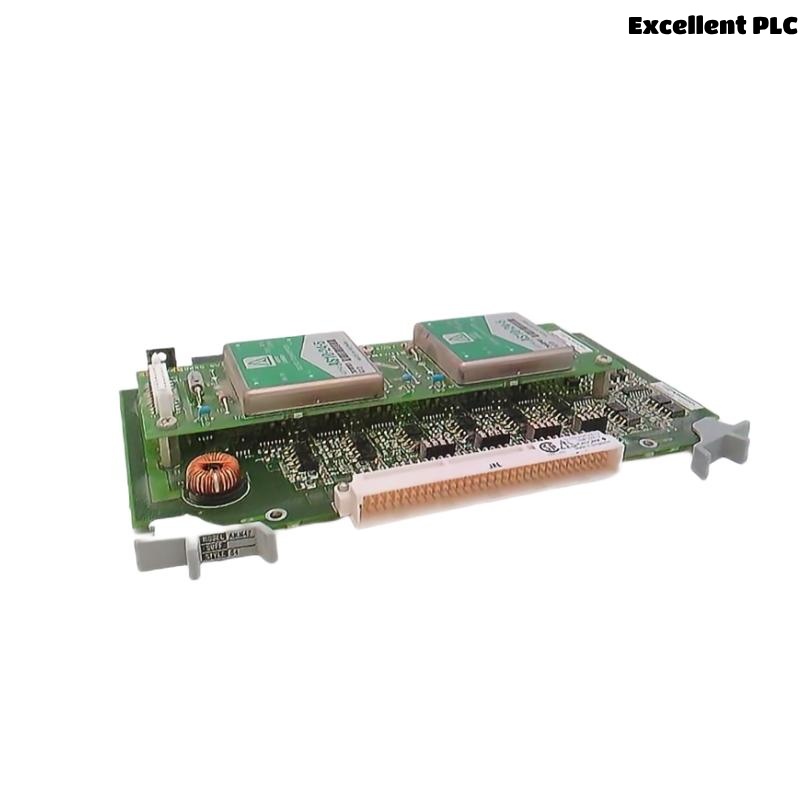
AMM42 Installation Overview
The YOKOGAWA AMM42 is a 2-wire transmitter input multiplexer module used in Yokogawa CENTUM distributed control systems for industrial process signal acquisition and analog input consolidation. The module is designed to receive multiple 4–20 mA DC transmitter signals used in process automation applications. :contentReference[oaicite:0]{index=0}
Proper installation directly affects analog signal accuracy, DCS communication stability, and process control reliability. Incorrect grounding continuity, unstable transmitter power supplies, and improper shield routing can create signal fluctuation and communication instability.
Multiplexer Input Module Function
- Receives multiple 2-wire transmitter input signals
- Supports 4–20 mA analog signal acquisition
- Reduces distributed control system I/O complexity
- Interfaces field transmitters with Yokogawa DCS systems
- Improves centralized process signal management
AMM42 Functional Features
- Supports up to 16 transmitter input channels
- Compatible with 4–20 mA DC analog signals
- 23.5–24.5 VDC transmitter power supply support
- 1-second data update period
- Industrial process automation integration capability
Yokogawa technical specifications identify the AMM42T as a 2-wire transmitter input/output multiplexer module supporting up to 16 channels of 4–20 mA DC process signals. :contentReference[oaicite:1]{index=1}
Pre-Installation Inspection Procedure
- Inspect module housing and terminal integrity
- Verify stable 24 VDC cabinet power distribution
- Check grounding continuity throughout the control cabinet
- Inspect shielded analog signal cable integrity
- Verify cabinet ventilation and thermal conditions
Module Installation and Rack Mounting
Proper mounting is essential for long-term analog signal stability and industrial automation reliability.
- Install the AMM42 securely into the designated I/O module nest
- Verify backplane connector engagement
- Maintain adequate airflow around the module
- Inspect terminal wiring before energizing the system
  // Multiplexer Startup Logic
  IF Cabinet_Power_OK = TRUE THEN
      Initialize_AMM42_Module();
      Verify_4_20mA_Input_Signals();
  ELSE
      Inspect_Power_Distribution();
  END_IF;
2-Wire Transmitter Wiring Requirements
- Use shielded twisted-pair analog signal cables
- Separate analog wiring from inverter and motor power cables
- Maintain proper grounding continuity
- Verify terminal tightness before startup
- Ground signal shielding at one side only
Yokogawa specifications indicate a transmitter power supply range of 23.5 to 24.5 VDC with input resistance of 250 Ω, adjustable to 70 Ω when used with barriers. :contentReference[oaicite:2]{index=2}
Signal Configuration and DCS Integration
- Configure analog signal scaling parameters
- Verify transmitter communication stability
- Inspect process signal update timing
- Validate stable DCS communication with field devices
Industrial Automation Commissioning
- Observe analog input stability during startup
- Verify process transmitter signal accuracy
- Check module diagnostic indicators
- Validate stable process data acquisition
Signal Stability Optimization Methods
- Improve cabinet grounding continuity
- Reduce EMI exposure near analog signal wiring
- Maintain stable environmental temperature conditions
- Record baseline signal calibration values
Industrial Application Example
During startup of a refinery automation system, unstable transmitter readings appeared intermittently:
- 4–20 mA process values fluctuated unexpectedly
- DCS operator stations displayed unstable measurements
Investigation identified:
- Analog cables routed beside VFD motor power wiring
- Improper grounding continuity inside the cabinet
After corrective actions:
- Separated analog and power cable routing
- Improved grounding continuity integrity
Result:
- Stable analog signal transmission restored
- Process control reliability improved significantly
Installation FAQ
What signal type does the AMM42 support?
The module supports 4–20 mA DC signals from 2-wire transmitters. :contentReference[oaicite:3]{index=3}
How many transmitter channels are supported?
Yokogawa documentation specifies support for up to 16 transmitter channels. :contentReference[oaicite:4]{index=4}
Why is shield grounding important?
Proper shield grounding minimizes EMI interference and improves analog signal stability.
Engineering Summary
The YOKOGAWA AMM42 Installation Guide demonstrates that reliable process signal acquisition depends on proper grounding continuity, optimized shielded cable routing, stable transmitter power supplies, and disciplined DCS commissioning procedures.