

Table of Contents
- VI451-10 Installation Overview
- Communication Module Function
- VI451-10 Functional Features
- Technical Specifications
- Pre-Installation Inspection Procedure
- Module Installation Procedure
- Industrial Communication Wiring Requirements
- DCS Communication Configuration
- Communication Commissioning Procedure
- Communication Reliability Optimization
- Industrial Application Example
- Installation FAQ
- Engineering Summary
VI451-10 Installation Overview
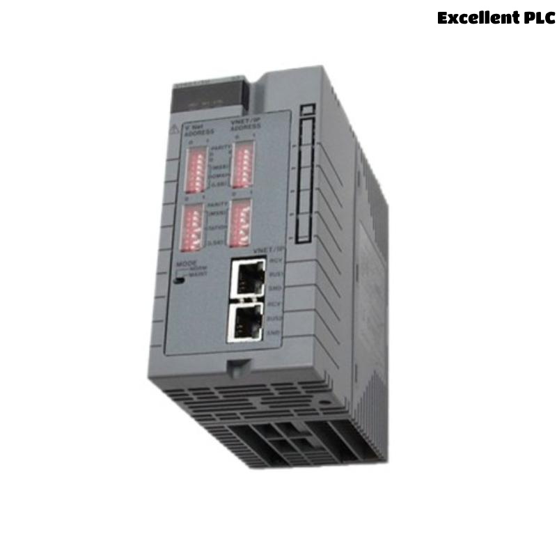
The YOKOGAWA VI451-10 is an industrial communication module designed for Yokogawa distributed control systems and process automation platforms. The module provides communication interface functionality between controllers, network infrastructure, and field-level automation devices, supporting reliable industrial data exchange within DCS architectures.
Proper installation directly affects communication reliability, controller synchronization, process data integrity, and network stability. Incorrect module insertion, loose communication connections, grounding defects, or EMI exposure may result in communication interruptions, network alarms, and process control instability.
Communication Module Function
- Provides industrial communication interface functionality
- Supports controller and network communication integration
- Maintains stable process data transmission
- Enables distributed automation communication
- Supports DCS communication infrastructure operation
VI451-10 Functional Features
- Industrial communication processing architecture
- High-reliability communication interface design
- EMI-resistant industrial communication circuitry
- Optimized for Yokogawa automation platforms
- Supports continuous industrial operation environments
Technical Specifications
- Model: VI451-10
- Product type: Communication Module
- Application: Industrial automation communication
- Installation method: Rack-mounted module installation
- Function: Communication interface and data exchange
- Compatible systems: Yokogawa DCS platforms
- Communication environment: Industrial control networks
- Protection design: Industrial EMI-resistant architecture
Yokogawa VI series communication modules are used to provide stable communication connectivity within distributed process automation systems and industrial control network infrastructures.
Pre-Installation Inspection Procedure
- Inspect module housing and communication interfaces
- Verify backplane connector integrity
- Check cabinet grounding continuity
- Inspect communication cable condition
- Verify communication topology requirements
Module Installation Procedure
Proper installation is essential for maintaining long-term communication stability and reliable industrial network operation.
- Power down the control system before installation
- Insert the VI451-10 into the designated communication slot
- Verify complete backplane connector engagement
- Secure the module using retention hardware
- Connect communication interfaces and inspect connector locking
  // Communication Startup Logic
  IF System_Power_OK = TRUE THEN
      Verify_VI451_10_Status();
      Check_Communication_Integrity();
  ELSE
      Inspect_Power_Distribution_System();
  END_IF;
Industrial Communication Wiring Requirements
- Use shielded industrial communication cables
- Separate communication wiring from power circuits
- Maintain stable grounding continuity
- Verify secure communication connector locking
- Maintain organized cable routing structure
Industrial communication systems require disciplined cable routing and grounding practices to minimize EMI interference and maintain stable process communication.
DCS Communication Configuration
- Configure communication network parameters
- Verify controller communication status
- Check network redundancy operation
- Validate process data synchronization
Communication Commissioning Procedure
- Observe communication stability during startup
- Verify controller communication operation
- Check communication diagnostic alarms
- Validate process data transmission performance
Communication Reliability Optimization
- Improve grounding continuity integrity
- Reduce EMI exposure near communication wiring
- Maintain secure communication interfaces
- Record baseline communication performance values
Industrial Application Example
During modernization of a petrochemical DCS network, intermittent communication instability appeared after adding new automation equipment:
- Communication alarms appeared intermittently
- Controller synchronization delays increased during motor startup
Investigation identified:
- Loose VI451-10 communication interface connections
- Communication wiring installed beside inverter power cables
After corrective actions:
- Re-secured communication interfaces
- Separated communication and power cable routing
Result:
- Stable communication operation restored
- DCS network reliability improved significantly
Installation FAQ
What is the primary function of the VI451-10?
The VI451-10 provides industrial communication interface functionality within Yokogawa distributed automation systems.
Why is proper grounding important?
Stable grounding continuity minimizes communication instability and improves network reliability.
Can EMI affect communication module performance?
Yes. Communication wiring installed near inverter or motor power cables may experience interference-related communication instability.
Engineering Summary
The YOKOGAWA VI451-10 Installation Guide demonstrates that reliable industrial communication depends on proper module installation, stable grounding continuity, optimized communication cable routing, and disciplined DCS integration practices.