

Yokogawa SPW484-53 power supply module installation issues are typically caused by incorrect input voltage verification, grounding deficiencies, or cabinet heat accumulation rather than defects in the power module itself. During DCS commissioning, stable power distribution is often the deciding factor between a successful startup and recurring system diagnostics.
Contents
- SPW484-53 Power Supply Module Overview
- Power System Preparation Before Installation
- SPW484-53 Installation Guide
- Power Module Setup and System Configuration
- Commissioning Verification Procedure
- Real Field Installation Experience
- FAQ
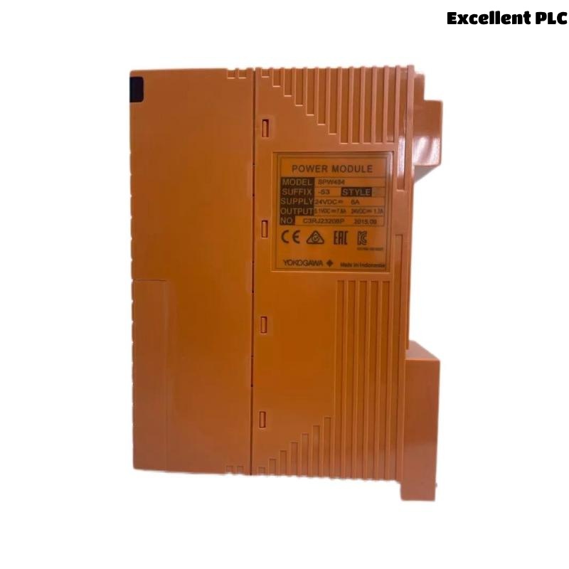
Yokogawa SPW484-53 Power Supply Module Overview
The Yokogawa SPW484-53 is an industrial Power Supply Module designed to provide stable DC power for control systems, field control units, and distributed I/O infrastructure. Depending on system architecture, the module is commonly used to maintain reliable voltage delivery for automation equipment operating in demanding industrial environments. Available technical references indicate the module is designed for industrial DC power applications with integrated protection functions and multi-voltage distribution capability. :contentReference[oaicite:0]{index=0}
Power System Preparation Before SPW484-53 Installation
Before installing the Power Supply Module, engineers should evaluate the complete power distribution architecture.
- Incoming power source verified
- Cabinet grounding inspected
- Load calculation completed
- Protection devices validated
- Redundancy requirements reviewed
- Power cable sizing confirmed
In many brownfield projects, undocumented field modifications create power loading conditions that exceed the original design assumptions.
SPW484-53 Power Supply Module Installation Guide
Mechanical Installation
- Isolate all power sources.
- Inspect module connectors.
- Mount the SPW484-53 securely.
- Verify cooling clearances.
- Confirm cabinet ventilation paths.
Electrical Wiring
Input and output wiring should be verified before energization.
- Check polarity carefully.
- Inspect terminal tightness.
- Verify protective earth continuity.
- Separate power and signal cables.
- Label all field connections.
Incorrect polarity remains one of the most common installation mistakes observed during startup activities.
SPW484-53 Setup and System Configuration
After installation, engineers should validate the power distribution network before connecting critical controllers and modules.
VERIFY INPUT VOLTAGE
CHECK OUTPUT VOLTAGE
VERIFY GROUNDING
MEASURE LOAD CURRENT
CHECK ALARM STATUS
RECORD BASELINE VALUES
System Configuration records should include measured voltage levels and load currents to simplify future troubleshooting activities.
SPW484-53 Commissioning Verification Procedure
A complete commissioning process should verify performance under realistic operating conditions.
- No-load voltage verification
- Loaded voltage verification
- Ground continuity testing
- Power quality monitoring
- Redundancy validation
- Temperature monitoring
Technical references indicate typical SPW484-53 implementations provide regulated DC outputs with protection against overvoltage and overcurrent conditions. :contentReference[oaicite:1]{index=1}
Real Commissioning Case with SPW484-53
During commissioning of a wastewater treatment control system, operators reported recurring communication alarms affecting multiple remote I/O stations.
Initial measurements showed:
- Input voltage: 24.1 VDC
- Output voltage: 23.7 VDC
- Cabinet temperature: 52°C
- Load current: 82% of rated capacity
The maintenance team initially suspected network hardware issues.
However, thermal imaging revealed restricted airflow caused by improperly installed cable ducts directly above the SPW484-53.
After improving ventilation:
- Cabinet temperature dropped to 36°C
- Output voltage stabilized
- Communication alarms disappeared
- System commissioning completed successfully
We observed that thermal stress on the power infrastructure produced symptoms that appeared unrelated to the power supply itself.
SPW484-53 Installation Guide FAQ
What should be verified before energizing the SPW484-53 Power Supply Module?
Engineers should verify input voltage, polarity, grounding continuity, cable terminations, and connected load requirements.
Why is temperature monitoring important during commissioning?
Excessive cabinet temperatures can affect long-term reliability and create intermittent operational issues.
Should voltage measurements be recorded after startup?
Yes. Baseline voltage and current values simplify future troubleshooting and preventive maintenance activities.
Summary: A successful Yokogawa SPW484-53 Installation Guide should focus on power quality, grounding integrity, thermal management, load verification, and commissioning validation to ensure long-term control system reliability.